(!)Due to Microsoft's end of support for Internet Explorer 11 on 15/06/2022, this site does not support the recommended environment.
Mon. - Fri. 8 a.m. - 6 p.m.
All Categories
-
Automation Components
Automation Components
Show all categories of Automation Components-
Linear Motion
-
Rotary Motion
-
Connecting Parts
-
Rotary Power Transmission
-
Motors
-
Conveyors & Material Handling
-
Locating, Positioning, Jigs & Fixtures
-
Inspection
-
Sensors, Switches
-
Pneumatics, Hydraulics
-
Vacuum Components
-
Hydraulic Equipment
-
Spray Equipment And Accessories
-
Pipe, Tubes, Hoses & Fittings
-
Modules, Units
-
Heaters, Temperature Control
-
Aluminum Extrusions, Framing, Support & Posts
-
Casters, Leveling Mounts, Posts
-
Doors, Cabinet Hardware
-
Springs, Shock Absorbers
-
Adjustment/Fastening Components, Pins, Magnets
-
Antivibration, Soundproofing Materials, Safety Products
-
- Fasteners
- Materials
-
Wiring Components
Wiring Components
Show all categories of Wiring Components-
LAN Cables / Industrial Network Cables
-
Equipment Specific Cables
-
Cordsets
-
Computer & AV Cables
-
Wire/Cable
-
Connector (General Purpose)
-
Crimp Terminal Components
-
Cable Organization
-
Cable Gland Components
-
Cable Bushing/Clip/Sticker
-
Screw/Spacer
-
Cable accessories
-
Tube
-
Electrical Conduits
-
Duct/Wiring
-
Electrical Wiring Tools
-
Dedicated tools
-
Soldering supplies
-
- Electrical & Controls
-
Cutting Tools
Cutting Tools
Show all categories of Cutting Tools-
Carbide End Mill
-
HSS End Mill
-
Concrete Drill Bits
-
Milling Cutter Insert / Holder
-
Core Drill Bits
-
Customized Straight Blade End Mill
-
Dedicated Cutter
-
Crinkey Cutters
-
Turning Tool
-
Drill
-
Cutting Tool Accessories
-
Screw Hole Related Tools
-
Reamer
-
Electric Drill Bits
-
Chamfering, Centering Tool
-
Hole Saws
-
Magnetic Drill Press Cutters
-
Step Drills
-
Wood Drills & Cutters
-
-
Processing Tools
- Packing & Logistics Storage Supplies
- Safety Products
-
Research and Development & Cleanroom Supplies
Research and Development & Cleanroom Supplies
Show all categories of Research and Development & Cleanroom Supplies - Press Die Components
-
Plastic Mold Components
Plastic Mold Components
Show all categories of Plastic Mold Components-
Ejector Pins
-
Sleeves, Center Pins
-
Core Pins
-
Sprue bushings, Gates, and other components
-
Date Mark Inserts, Recycle Mark Inserts, Pins with Gas Vent
-
Undercut, Plates
-
Leader Components, Components for Ejector Space
-
Mold Opening Controllers
-
Cooling or Heating Components
-
Accessories, Others
-
Components of Large Mold, Die Casting
-
-
Injection Molding Components
Injection Molding Components
Show all categories of Injection Molding Components-
Purging Agent
-
Injection Molding Machine Products
-
Accessories of Equipment
-
Auxiliary Equipment
-
Air Nippers
-
Air Cylinders
-
Air Chuck for Runner
-
Chuck Board Components
-
Frames
-
Suction Components
-
Parallel Air Chuck
-
Special Air Chuck
-
Mold Maintenance
-
Heating Items
-
Heat Insulation Sheets
-
Couplers, Plugs, One-touch Joints
-
Tubes, Hoses, Peripheral Components
-
- Webcode Seach | Series
-
#CODE
- Discontinued Products
Loading...
- inCAD Library Home
- > No.000028 Vertical Feed Mechanism
No.000028 Vertical Feed Mechanism
13
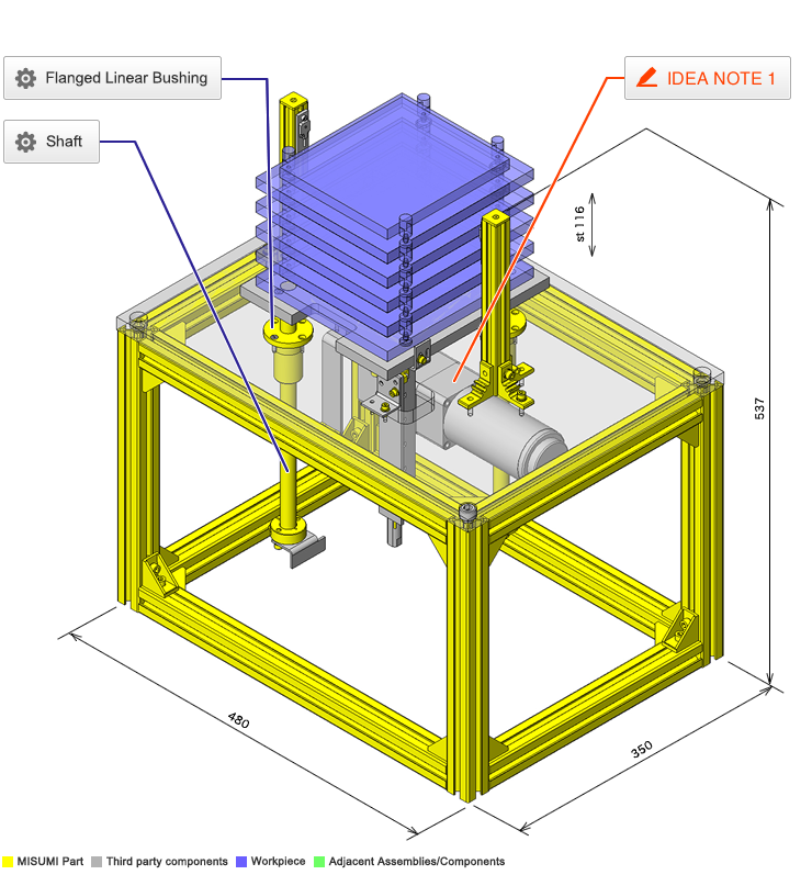
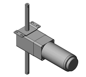
Vertical feed with a linear motion gearhead and motor
Relevant category
- * Unit assembly Data consists of some sub-assemblies.
It is configured so that each sub-assembly unit can be used as it is or edited.
Application Overview
Purpose
- Workpieces on platform can be raised to adjustable height.
- Self-locking type motor prevents falling.
Target workpiece
- Workpiece
- External dims.: W147 x D167 x H12
- Weight: 0.3kg
- Tray
- External dims.: W180 x D200 x H179
- Weight: 0.6kg
- Max. weight
(5 workpieces + 5 Trays)
(0.3 x 5) + (0.6 x 5) = 4.5kg
Design Specifications
Operating Conditions or Design Requirements
- Slide stroke: 116mm (Pitch 29mm x 4)
- External dims.: W480 x D350 x H537
Required Performance
- Total transferred mass: 16 kg or less
Selection Criteria for Main Components
- Motor
- Load retaining type is selected to prevent falling due to own weight.
- Linear motion gearhead
- Vertical motion type is selected to move the workpieces up/down.
- Sensor
- 2 output type sensor is selected for pitch feeding.
Design Evaluation
Verification of main components
- Verify the motor regarding required speed and load capacity.
- Rack speed
- Motor speed (Ns): 90~1600 r/min
- Reduction ratio of linear motion gearhead (i): 35.36
- Pitch circle DIA. of the pinion (Dp): 12mm
- Rack speed (V)
V = Ns × (1 / 60) × (1 / i) × π × Dp - Vmin = 90 × (1 / 60) × (1 / 35.36) × π × 12 = 1.6 mm/s
- Vmax = 1600 × (1 / 60) × (1 / 35.36) × π × 12 = 28.43 mm/s
- Assumed rack speed: 15mm/s, OK.
- Max. payload
- Motor torque Tm: 45N・m
- Reduction ratio of linear motion gearhead (i): 35.36
- Pitch circle DIA. of the pinion (Dp): 12mm
- Transmission efficiency by reduction ratio (η1) : 0.66
- Transmission efficiency of rack and pinion (η2): 0.9
- The maximum allowable load capacity (W):
W = Tm × I × η1 / (Dp / 2) × η2 / 9.8 = 45 × 35.36 × 0.66 / (12 / 2) × 0.9 / 9.8 = 16 kg
Total elevating mass: Workpiece + Tray + Base + Rack + Others = 4.5 + 1.3 + 1 + 2 = 8.8 kg < 16 kg
Other Design Consideration
- Pitch feeding is possible when using a photomicro sensor to detect the pitch.
- The lower most tray and the upper most tray are detected by a photoelectric switch.
- For detecting the lower most limit, another sensor and pitch detection plate are placed (Limit switch).
- For detecting the upper most limit, another sensor and a sensor flag are placed (Limit switch)
Explore Similar Application Examples
-
Relevant category
-
Relevant category
-
Relevant category


