(!)Due to Microsoft's end of support for Internet Explorer 11 on 15/06/2022, this site does not support the recommended environment.
Mon. - Fri. 8 a.m. - 6 p.m.
All Categories
-
Automation Components
Automation Components
Show all categories of Automation Components-
Linear Motion
-
Rotary Motion
-
Connecting Parts
-
Rotary Power Transmission
-
Motors
-
Conveyors & Material Handling
-
Locating, Positioning, Jigs & Fixtures
-
Inspection
-
Sensors, Switches
-
Pneumatics, Hydraulics
-
Vacuum Components
-
Hydraulic Equipment
-
Spray Equipment And Accessories
-
Pipe, Tubes, Hoses & Fittings
-
Modules, Units
-
Heaters, Temperature Control
-
Aluminum Extrusions, Framing, Support & Posts
-
Casters, Leveling Mounts, Posts
-
Doors, Cabinet Hardware
-
Springs, Shock Absorbers
-
Adjustment/Fastening Components, Pins, Magnets
-
Antivibration, Soundproofing Materials, Safety Products
-
- Fasteners
- Materials
-
Wiring Components
Wiring Components
Show all categories of Wiring Components-
LAN Cables / Industrial Network Cables
-
Equipment Specific Cables
-
Cordsets
-
Computer & AV Cables
-
Wire/Cable
-
Connector (General Purpose)
-
Crimp Terminal Components
-
Cable Organization
-
Cable Gland Components
-
Cable Bushing/Clip/Sticker
-
Screw/Spacer
-
Cable accessories
-
Tube
-
Electrical Conduits
-
Duct/Wiring
-
Electrical Wiring Tools
-
Dedicated tools
-
Soldering supplies
-
- Electrical & Controls
-
Cutting Tools
Cutting Tools
Show all categories of Cutting Tools-
Carbide End Mill
-
HSS End Mill
-
Concrete Drill Bits
-
Milling Cutter Insert / Holder
-
Core Drill Bits
-
Customized Straight Blade End Mill
-
Dedicated Cutter
-
Crinkey Cutters
-
Turning Tool
-
Drill
-
Cutting Tool Accessories
-
Screw Hole Related Tools
-
Reamer
-
Electric Drill Bits
-
Chamfering, Centering Tool
-
Hole Saws
-
Magnetic Drill Press Cutters
-
Step Drills
-
Wood Drills & Cutters
-
-
Processing Tools
- Packing & Logistics Storage Supplies
- Safety Products
-
Research and Development & Cleanroom Supplies
Research and Development & Cleanroom Supplies
Show all categories of Research and Development & Cleanroom Supplies - Press Die Components
-
Plastic Mold Components
Plastic Mold Components
Show all categories of Plastic Mold Components-
Ejector Pins
-
Sleeves, Center Pins
-
Core Pins
-
Sprue bushings, Gates, and other components
-
Date Mark Inserts, Recycle Mark Inserts, Pins with Gas Vent
-
Undercut, Plates
-
Leader Components, Components for Ejector Space
-
Mold Opening Controllers
-
Cooling or Heating Components
-
Accessories, Others
-
Components of Large Mold, Die Casting
-
-
Injection Molding Components
Injection Molding Components
Show all categories of Injection Molding Components-
Purging Agent
-
Injection Molding Machine Products
-
Accessories of Equipment
-
Auxiliary Equipment
-
Air Nippers
-
Air Cylinders
-
Air Chuck for Runner
-
Chuck Board Components
-
Frames
-
Suction Components
-
Parallel Air Chuck
-
Special Air Chuck
-
Mold Maintenance
-
Heating Items
-
Heat Insulation Sheets
-
Couplers, Plugs, One-touch Joints
-
Tubes, Hoses, Peripheral Components
-
- Webcode Seach | Series
-
#CODE
- Discontinued Products
Loading...
- inCAD Library Home
- > No.000230 Adjustable Guide Mechanism
No.000230 Adjustable Guide Mechanism
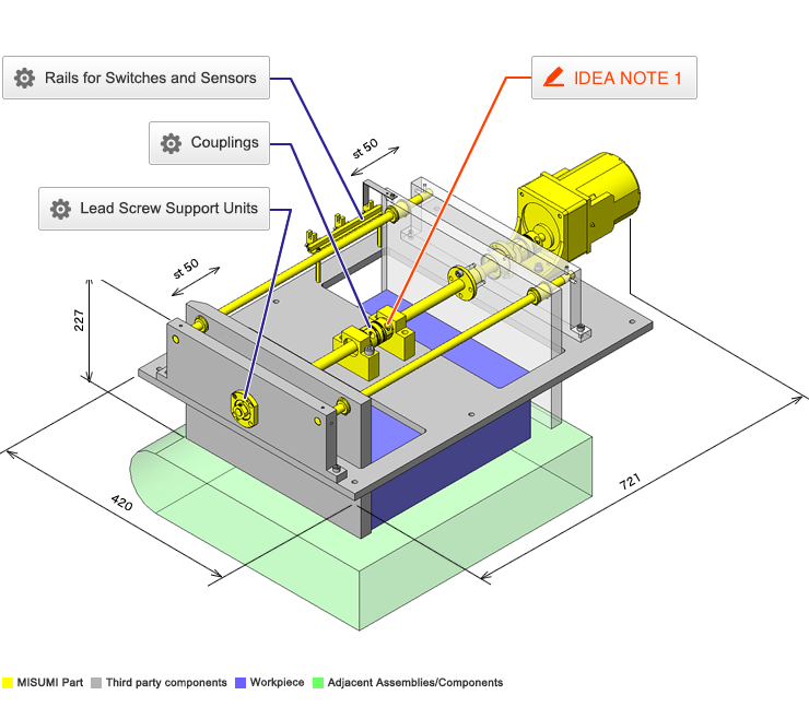
Easy adjustment using coupling, motor and lead screws.
Relevant category
- * Unit assembly Data consists of some sub-assemblies.
It is configured so that each sub-assembly unit can be used as it is or edited.
Application Overview
Purpose
- Purpose
- To automatically change the distance between workpiece guides during setup change.
- Operation
- By connecting right and left hand screw with coupling and rotating only one lead screw, the distance between guide plates is adjusted without changing the center of reference.
Points for use
- Thanks to the coupling that connects the lead screws, adjusting only one side will also adjust the side, maintaining the center between the guide plates.
Target workpiece
- Shape: cardboard box
- Size: W330 x D280 x H110 mm
- Weight: 2 kg
Design Specifications
Operating Conditions or Design Requirements
- Target workpiece width range: 230 to 330 mm
- Outer dimensions: W721 x D420 x H227 mm
Required Performance
- Lead Screw
Single pitch error:±0.02mm
Accumulated pitch error: ±0.15/300 mm
Allowable Load:33.8kg
Selection Criteria for Main Components
- Coupling
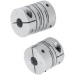
- A coupling with an allowable torque of 4 [N·m], small backlash backlash and an allowable torque of 0.66 [N·m] is selected.
Design Evaluation
Verification of main components
- Select motor, lead screws and linear bushings based on the workpiece load and workpiece collision load.
- Confirmation of thrust in axial direction
- Conditional value: workpiece mass W = 2kg, gravitational acceleration g = 9.8m/s², friction coefficient of lead screw μ = 0.21, lead of lead screw: R = 3mm = 0.003m, lead angle of lead screw: θ = 3.77°, rated torque of geared motor with reduction ratio i = 3: T = 0.66N·m, friction coefficient exerted on workpiece: δ = 0.5
- Screw efficiency η
η=(1-μ×tanθ)/(1+μ/tanθ)=(1-0.21×tan3.77)/(1+0.21/tan3.77)=0.24
Thrust of lead screw:F=2π×η×T/R=2π×0.24×0.66/0.003
=331.8N - Force required to move workpiece: P
P=M×g×σ=2×9.8×0.5=9.8N and F > P, the necessary force can be obtained.
- Allowable load of linear ball bushing when workpiece hits the guide
- Conditional value: linear bushing maximum horizontal distance X0 = 370.4 mm, linear bushing distance in transfer direction Y0 = 276 mm, distance between transfer axis and load position X1 = 180 mm, vertical distance between linear bushing axis and load position L0 = 170.5 mm, load applied when workpiece collides Wa = 40 N, basic rated static load of liner bushing C0 = 598 N, number of linear bushings to which load is applied when workpiece collides N = 2 pieces
- Load in transfer direction applied to linear bushing on collision side: Ps=(W/N)+{(X1×W)/2×X0}=(40/2)+{(180×40)/(2×370.4)}=29.72N
- Load in vertical direction applied to linear bushing on collision side: Pn={(L0×W)/(2×Y0)}={(170.5×40)/(2×276)}=12.36N
Therefore, resultant force applied to linear bushing:P=√(Ps2+Pn2)=32.19N<598=CO (Bushing Dynamic load rating)
Other Design Consideration
- For applications where only small adjustments are needed it is possible to substitute one left and one right hand screw with right/left hand screw and avoid center block and coupling.
Explore Similar Application Examples
-
Relevant category
-
Relevant category


