(!)Due to Microsoft's end of support for Internet Explorer 11 on 15/06/2022, this site does not support the recommended environment.
Mon. - Fri. 8 a.m. - 6 p.m.
All Categories
-
Automation Components
Automation Components
Show all categories of Automation Components-
Linear Motion
-
Rotary Motion
-
Connecting Parts
-
Rotary Power Transmission
-
Motors
-
Conveyors & Material Handling
-
Locating, Positioning, Jigs & Fixtures
-
Inspection
-
Sensors, Switches
-
Pneumatics, Hydraulics
-
Vacuum Components
-
Hydraulic Equipment
-
Spray Equipment And Accessories
-
Pipe, Tubes, Hoses & Fittings
-
Modules, Units
-
Heaters, Temperature Control
-
Aluminum Extrusions, Framing, Support & Posts
-
Casters, Leveling Mounts, Posts
-
Doors, Cabinet Hardware
-
Springs, Shock Absorbers
-
Adjustment/Fastening Components, Pins, Magnets
-
Antivibration, Soundproofing Materials, Safety Products
-
- Fasteners
- Materials
-
Wiring Components
Wiring Components
Show all categories of Wiring Components-
LAN Cables / Industrial Network Cables
-
Equipment Specific Cables
-
Cordsets
-
Computer & AV Cables
-
Wire/Cable
-
Connector (General Purpose)
-
Crimp Terminal Components
-
Cable Organization
-
Cable Gland Components
-
Cable Bushing/Clip/Sticker
-
Screw/Spacer
-
Cable accessories
-
Tube
-
Electrical Conduits
-
Duct/Wiring
-
Electrical Wiring Tools
-
Dedicated tools
-
Soldering supplies
-
- Electrical & Controls
-
Cutting Tools
Cutting Tools
Show all categories of Cutting Tools-
Carbide End Mill
-
HSS End Mill
-
Concrete Drill Bits
-
Milling Cutter Insert / Holder
-
Core Drill Bits
-
Customized Straight Blade End Mill
-
Dedicated Cutter
-
Crinkey Cutters
-
Turning Tool
-
Drill
-
Cutting Tool Accessories
-
Screw Hole Related Tools
-
Reamer
-
Electric Drill Bits
-
Chamfering, Centering Tool
-
Hole Saws
-
Magnetic Drill Press Cutters
-
Step Drills
-
Wood Drills & Cutters
-
-
Processing Tools
- Packing & Logistics Storage Supplies
- Safety Products
-
Research and Development & Cleanroom Supplies
Research and Development & Cleanroom Supplies
Show all categories of Research and Development & Cleanroom Supplies - Press Die Components
-
Plastic Mold Components
Plastic Mold Components
Show all categories of Plastic Mold Components-
Ejector Pins
-
Sleeves, Center Pins
-
Core Pins
-
Sprue bushings, Gates, and other components
-
Date Mark Inserts, Recycle Mark Inserts, Pins with Gas Vent
-
Undercut, Plates
-
Leader Components, Components for Ejector Space
-
Mold Opening Controllers
-
Cooling or Heating Components
-
Accessories, Others
-
Components of Large Mold, Die Casting
-
-
Injection Molding Components
Injection Molding Components
Show all categories of Injection Molding Components-
Purging Agent
-
Injection Molding Machine Products
-
Accessories of Equipment
-
Auxiliary Equipment
-
Air Nippers
-
Air Cylinders
-
Air Chuck for Runner
-
Chuck Board Components
-
Frames
-
Suction Components
-
Parallel Air Chuck
-
Special Air Chuck
-
Mold Maintenance
-
Heating Items
-
Heat Insulation Sheets
-
Couplers, Plugs, One-touch Joints
-
Tubes, Hoses, Peripheral Components
-
- Webcode Seach | Series
-
#CODE
- Discontinued Products
Loading...
- inCAD Library Home
- > No.000041 Pallet Transfer Anti-reversing Mechanism
No.000041 Pallet Transfer Anti-reversing Mechanism
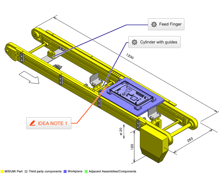
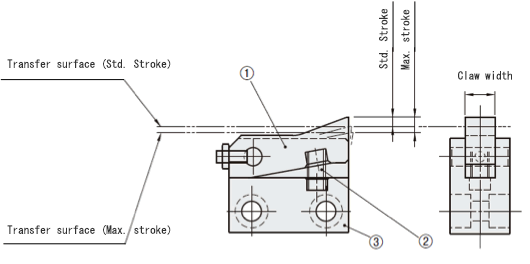
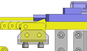
Feed fingers prevent pallets from reverse flowing
Relevant category
- * Unit assembly Data consists of some sub-assemblies.
It is configured so that each sub-assembly unit can be used as it is or edited.
Application Overview
Purpose
- Prevent pallets from reverse flowing.
Target workpiece
- Plastic case size: W120 x D220 x H20 mm
- Pallet size: W218 x D300 x t12 mm (Aluminum)
- Weight of transferred object: 2.3kg/pc.
Design Specifications
Operating Conditions or Design Requirements
- Conveyor size: W283 x D1270 x H185 mm
- Transfer speed: 150mm/s
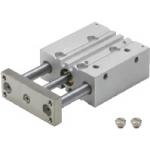
- Stopper cylinder stroke: 20 mm
Required Performance
- Pallet positioning accuracy: ±0.5 mm
Selection Criteria for Main Components
- Two row type conveyor is selected since the cylinder and feed fingers are located below the transfer surface.
Design Evaluation
Verification of main components
- Verify that the plastic chain conveyor can withstand the workpiece load.
- Plastic chain conveyor
- Transferred weight: 2.3kg x 3pcs. (max.) = 6.9kg
- Transfer speed: 150mm/s = 9m/min
- Based on conveyor transferability graph above conditions fall within the range for 25W conveyor.
Other Design Consideration
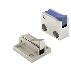
- A stopper with a cylinder is placed at the fore direction of travel. Pallet reverse flowing is prevented by a feed finger located at the back.
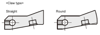
- If scratching the pallets is a concern, use feed fingers with Nylon claws.
Explore Similar Application Examples
-
Relevant category
-
Relevant category
-
Relevant category


