(!)Due to Microsoft's end of support for Internet Explorer 11 on 15/06/2022, this site does not support the recommended environment.
Mon. - Fri. 8 a.m. - 6 p.m.
All Categories
-
Automation Components
Automation Components
Show all categories of Automation Components-
Linear Motion
-
Rotary Motion
-
Connecting Parts
-
Rotary Power Transmission
-
Motors
-
Conveyors & Material Handling
-
Locating, Positioning, Jigs & Fixtures
-
Inspection
-
Sensors, Switches
-
Pneumatics, Hydraulics
-
Vacuum Components
-
Hydraulic Equipment
-
Spray Equipment And Accessories
-
Pipe, Tubes, Hoses & Fittings
-
Modules, Units
-
Heaters, Temperature Control
-
Aluminum Extrusions, Framing, Support & Posts
-
Casters, Leveling Mounts, Posts
-
Doors, Cabinet Hardware
-
Springs, Shock Absorbers
-
Adjustment/Fastening Components, Pins, Magnets
-
Antivibration, Soundproofing Materials, Safety Products
-
- Fasteners
- Materials
-
Wiring Components
Wiring Components
Show all categories of Wiring Components-
LAN Cables / Industrial Network Cables
-
Equipment Specific Cables
-
Cordsets
-
Computer & AV Cables
-
Wire/Cable
-
Connector (General Purpose)
-
Crimp Terminal Components
-
Cable Organization
-
Cable Gland Components
-
Cable Bushing/Clip/Sticker
-
Screw/Spacer
-
Cable accessories
-
Tube
-
Electrical Conduits
-
Duct/Wiring
-
Electrical Wiring Tools
-
Dedicated tools
-
Soldering supplies
-
- Electrical & Controls
-
Cutting Tools
Cutting Tools
Show all categories of Cutting Tools-
Carbide End Mill
-
HSS End Mill
-
Concrete Drill Bits
-
Milling Cutter Insert / Holder
-
Core Drill Bits
-
Customized Straight Blade End Mill
-
Dedicated Cutter
-
Crinkey Cutters
-
Turning Tool
-
Drill
-
Cutting Tool Accessories
-
Screw Hole Related Tools
-
Reamer
-
Electric Drill Bits
-
Chamfering, Centering Tool
-
Hole Saws
-
Magnetic Drill Press Cutters
-
Step Drills
-
Wood Drills & Cutters
-
-
Processing Tools
-
Packing & Logistics Storage Supplies
- Safety Products
-
Research and Development & Cleanroom Supplies
Research and Development & Cleanroom Supplies
Show all categories of Research and Development & Cleanroom Supplies - Press Die Components
-
Plastic Mold Components
Plastic Mold Components
Show all categories of Plastic Mold Components-
Ejector Pins
-
Sleeves, Center Pins
-
Core Pins
-
Sprue bushings, Gates, and other components
-
Date Mark Inserts, Recycle Mark Inserts, Pins with Gas Vent
-
Undercut, Plates
-
Leader Components, Components for Ejector Space
-
Mold Opening Controllers
-
Cooling or Heating Components
-
Accessories, Others
-
Components of Large Mold, Die Casting
-
-
Injection Molding Components
Injection Molding Components
Show all categories of Injection Molding Components-
Purging Agent
-
Injection Molding Machine Products
-
Accessories of Equipment
-
Auxiliary Equipment
-
Air Nippers
-
Air Cylinders
-
Air Chuck for Runner
-
Chuck Board Components
-
Frames
-
Suction Components
-
Parallel Air Chuck
-
Special Air Chuck
-
Mold Maintenance
-
Heating Items
-
Heat Insulation Sheets
-
Couplers, Plugs, One-touch Joints
-
Tubes, Hoses, Peripheral Components
-


- Webcode Seach | Series
-
#CODE
- Discontinued Products
Loading...

- inCAD Library Home
- > No.000216 90-Degree Pallet Transfer Mechanism
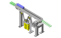
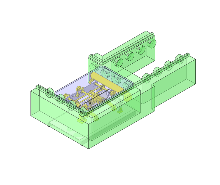
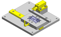
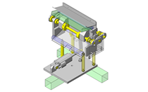
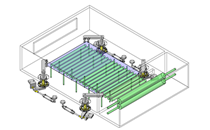
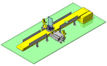
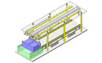
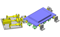
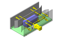
No.000216 90-Degree Pallet Transfer Mechanism
Transferring pallets at 90-degree without de-energizing the conveyors.
Relevant category


Motor Rollers
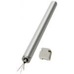
| Product name | Powered Rollers (with built-In Motor) |
|---|---|
| Part number | MOR42.7-300-10 |
| Features | Conveyor Roller with a built-in motor and a reducer. This does not require the separate space to be held for the motor and thus, helps space saving. |
Selection criteria
Space saving design - no need to prepare a motor space separately
Available sizes
■Powered Rollers (with built-In Motor)
| Roller Dia. | Length | Nominal Velocity | Power Supply | Rated Current | Speed(m/min) | Tangential Force (N) | Torque(N・m) | Roller Strength | |||||||||
|---|---|---|---|---|---|---|---|---|---|---|---|---|---|---|---|---|---|
| 50Hz | 60Hz | 50Hz | 60Hz | 50Hz | 60Hz | Length 300 | Length 400 | Length 500 | |||||||||
| Rating | Starting | Rating | Starting | Rating | Starting | Rating | Starting | ||||||||||
| 38 | 300 400 500 | 10 | Three-phase 200V 50/60Hz input 16/12W | 0.055/ 0.050 (A) | 10.4 | 13.1 | 16.7 | 12.4 | 12.4 | 31.3 | 31.8 | 70.9 | 23.6 | 59.6 | 343 | 294 | 294 |
| 15 | 14.2 | 16.1 | 12.3 | 9.2 | 9.2 | 30.9 | 23.3 | 75.3 | 17.5 | 58.7 | |||||||
| 20 | 22.2 | 25.2 | 7.8 | 5.8 | 5.8 | 19.7 | 14.9 | 48.0 | 11.1 | 37.4 | |||||||
| 42.7 | 300 400 500 | 10 | Three-phase 200V 50/60Hz input 18/17W | 0.065/ 0.062 (A) | 12.3 | 14.0 | 14.2 | 14.2 | 14.2 | 23.4 | 30.3 | 65.5 | 30.3 | 50.1 | 490 | 441 | 392 |
| 15 | 18.2 | 20.7 | 9.6 | 9.6 | 9.6 | 15.9 | 20.5 | 44.4 | 20.5 | 33.9 | |||||||
| 20 | 24.8 | 28.3 | 7.0 | 7.0 | 7.0 | 11.6 | 15.0 | 32.5 | 15.0 | 24.8 | |||||||
| 57 | 300 400 500 | 10 | Three-phase 200V 50/60Hz input 33/27W | 0.120/ 0.100 (A) | 11.2 | 13.3 | 37.0 | 37.0 | 37.0 | 78.4 | 126.8 | 236.8 | 105.4 | 223.4 | 980 | 980 | 784 |
| 15 | 12.4 | 14.8 | 33.5 | 33.5 | 33.5 | 67.6 | 114.5 | 214.1 | 95.4 | 192.6 | |||||||
| 20 | 17.0 | 20.2 | 24.5 | 24.5 | 24.5 | 49.5 | 83.7 | 156.7 | 69.8 | 141.0 | |||||||
Selection steps
(1) Calculate the required tangential force (roller carrying capability)
♦ Formula for the Required Tangential Force
Required tangential force (N) = 9.8 (constant value) x conveyed object weight (kg) x rolling friction coefficient
♦ Rolling Friction Coefficient Table
| Wood | Metal | Cardboard | Plastic | Rubber Lining |
|---|---|---|---|---|
| 0.02~0.05 | 0.01~0.02 | 0.05~1 | 0.02~0.04 | 0.1 |
Above values vary depending on the roller pitch or the roller surface conditions, etc.
Calculation example) When carrying a cardboard box weighing 40kg:
From the above Rolling Friction Coefficient Table, maximum friction coefficient for cardboard is 0.10.
Required tangential force=9.8×40kg×0.10=39.2N
* Rolling friction coefficient depends on the material of the object. Refer to the table above.
(2) Select the model temporarily
temporarily select the model that matches the speed from the specification table.
Ex. When carrying the objects at the speed of 20m/min, the part number is MOR57−(length)-20.
(3) Determine the number of required rollers
Determine the number of required rollers considering the following 2 elements.
●·Motor roller tangential force (start-up or at rated output) ● Carried weight and allowable static load of the roller (Please see the specification table "Roller Strength (N)".)
♦ Calculating the required tangential force
Carrying capability (N) = Starting tangential force of the motor roller (N) x 0.9 (constant value)
♦ Determine the number of required rollers
The number of required rollers = required tangential force (N) / carrying capability (N)
Calculation example) Required tangential force for conveying the object is 39.2N from the sample calculation above.
For the part number MOR57-(length)-20:
●·Carrying capability is 55 (N) (starting tangential force) x 0.9 = 49.5 (N).
● The number of required rollers is 39.2N (required tangential force) / 49.5N (carrying capability) = 0.79pcs. <- Can be transported by one roller
(4) Determine the length of the rollers
●·From the size of the bottom surface (length x width) of the object
Calculation example) When the length of the bottom surface is 300 mm and the width is 400 mm:
● The width of the object is 400mm + Margin 100mm = 500mm.
It follows that in this case, the part number should be MOR57-500-20.
Caution in Selection
● The calculated value using carrying tangential force gives the minimum value for required tangential force needed to carry the work.
Carrying capability could vary depending on roller level differences, carried object bottom surface shape (conditions),
material and motor roller speed, etc. Please use more rollers depending on usage conditions and considering safety.
If rated speed is important, use rated tangential force for calculation.
● When motor rollers are loaded at all times, use rated tangential force in calculating for selection.
● The object is assumed to start from on the motor rollers.
■Features
- The built-in motor and gear will save space
of the drive section.
- Requires no maintenance such as lubrication.
- Using the multiple motor rollers according to the object size
can avoid stopping the production line
even if one roller fails.

Shaft Collar

| Product name | Shaft Collars - 2 Tapped Holes |
|---|---|
| Part number | PSCSW10-10 |
Selection criteria
Easy-to-use stopper in the axial direction for shafts
Available sizes
■Shaft Collars - 2 Tapped Holes
| Material | Surface Treatment |
|---|---|
| 1045 Carbon Steel | Black Oxide |
| Electroless Nickel Plating | |
| 304 Stainless Steel | - |
■Sizes and Dimensions
| I.D. (mm) | Thickness (mm) | O.D. (mm) |
|---|---|---|
| 6 | 8 | 20 |
| 10 | ||
| 8 | 8 | 25 |
| 10 | ||
| 12 | 30 | |
| 10 | 8 | |
| 10 | ||
| 12 | ||
| 12 | 8 | |
| 10 | ||
| 12 | ||
| 15 | 35 | |
| 13 | 10 | 30 |
| 12 | ||
| 15 | 10 | 34 |
| 12 | 35 | |
| 15 | 40 | |
| 16 | 10 | 35 |
| 12 | ||
| 15 | 40 | |
| 18・20 | 10 | |
| 12 | ||
| 15 | 45 | |
| 25 | 12 | |
| 15 | 50 | |
| 30 | 15 | 55 |
Accuracy Info
■Accuracy of shaft collars
| I.D. (mm) | I.D. Tolerance (mm) |
|---|---|
| 6 | +0.05 +0.01 |
| 8 | |
| 10 | |
| 12 | |
| 13 | |
| 15 | |
| 16 | |
| 18・20 | |
| 25 | |
| 30 |

Urethane Rollers
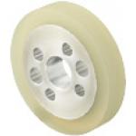
| Product name | Urethane Rollers - Side Through Hole |
|---|---|
| Part number | ULSH-40-10 |
Selection criteria
The roller guide that can transport the object without damaging it.
Available sizes
■Urethane Rollers - Side Through Hole
| Core | Lining | Hardness |
|---|---|---|
| 5052 Aluminum Alloy | Urethane | A90 |
■Sizes and Dimensions
| O.D. | I.D. | Side Through Hole (4-Hole) | Side Through Hole (2-Hole) |
|---|---|---|---|
| φ40 | φ10 | φ4.5 | φ5.5 |
| φ12 | φ5.5 | φ5.5 | |
| φ50 | φ12 | ||
| φ15 | |||
| φ60 | φ15 | ||
| φ20 | φ6.5 | φ6.5 | |
| φ70 | φ15 | φ5.5 | φ5.5 |
| φ20 | φ6.5 | φ6.5 | |
| φ80 | φ20 | ||
| φ25 |

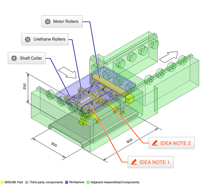
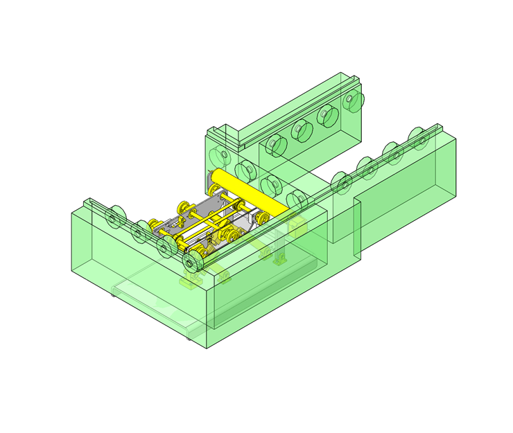
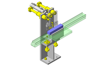
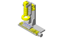
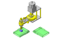
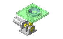
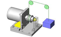
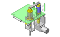
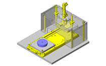
IDEA NOTE Powering drive roller.
The motor roller is fixed to the oscillating lever with a spring load applied to it, and the driving force is obtained by pressing the drive roller against the motor roller. The drive roller rotates when pressed with the motor roller and stops when released from it.


-

-
 Terms of Use for CAD Data and Simplified Drawing Data
- These terms and conditions (hereinafter referred to as “the Terms") set forth the conditions for downloading CAD data and simplified drawing data posted on https://mx.misumi-ec.com/ (hereinafter referred to as the "Website") operated by MISUMI MÉXICO, S. DE R.L. DE C.V. (hereinafter referred to as "MISUMI"). By downloading CAD data and simplified drawing data posted on the Website (hereafter referred to as “Data”), customers are deemed to have agreed to these Terms.
- 1. Purpose of Use
-
MISUMI offers the following:
1) CAD data found on the Website (3D CAD data, 3D Intermediate data and 2D CAD data) for the purpose of informing customers of the characteristics of the products offered by MISUMI or a manufacturer affiliated with MISUMI for use in their designs.
2) Simplified drawing data (in PDF format) for the purpose of checking the specifications of products. - 2. Characteristics of Data
- There may be a discrepancy in certain characteristics of products (for example: tolerance, surface roughness, chamfer, etc.) between the Data and the actual product. Furthermore, for the purpose of reducing the file size of the Data, some information such as oil groove shapes, threads, or spring shapes, may be removed from the Data.
- 3. Disclaimer
- MISUMI carefully creates the Data but makes no warranty as to the accuracy of the Data. MISUMI may at any time, and with no prior notice to customers, revise or delete Data. MISUMI assumes no responsibility for any damage or loss resulting from any revision or deletion of the Data, or any errors in said data. Customers are solely responsible for all aspects of their own designs, including those made using MISUMI’s CAD data. MISUMI may provide customers with design example data on the Website, but the quality, accuracy, functionality, safety, reliability, etc., of such data are not guaranteed. MISUMI may, at any time, and in its sole discretion, request that the customer cease its use of or destroy the Data in its possession. MISUMI may request the customer provide MISUMI documentation of such destruction.
- 4. Prohibited Acts
-
Customers or users of the Data, are prohibited from the following acts regarding the Data, in whole or in part:
(1) Requesting quotations or placing orders for products with third parties other than those authorized by MISUMI or its affiliates;
(2) Receiving quotations or orders for products from third parties by providing the Data to a third party or using the Data in their own business;
(3) Displaying links to the Website related to the Data on their own websites, etc., without MISUMI's consent;
(4) Using or reproducing the Data beyond the scope of the above-stated Purpose of Use;
(5) Modifying, altering, tampering with, translating, or adapting the Data;
(6) Selling, transferring, lending, sublicensing, or providing the Data to third parties in any way without MISUMI’s consent;
(7) Altering the content, reverse engineering, decompiling, disassembling, or analyzing the Data;
(8) Publicly disclosing or exhibiting the Data without MISUMI's consent;
(9) Using the Data for the purpose of providing products and services identical or similar to those of MISUMI;
(10) Performing acts that interfere with the proper functioning of this Website, such as acquiring Data in bulk. - 5. Copyright
-
All title and copyright in and to any information contained in the Data are owned by MISUMI or the relevant manufacturer affiliated with MISUMI and are protected by applicable copyright laws and international treaties. By downloading Data, the customer acquires no ownership rights of any kind in the intellectual property contained within. Without prior approval from MISUMI, no part of the Data may be utilized (reproduced, modified, reverse-engineered, uploaded, presented, sent, distributed, licensed, sold, or published) for any purpose other than that mentioned above.
In the event Data is found to have been to be used for any purpose other than that mentioned above or against any applicable laws, MISUMI may pursue any legal remedy available to it, which may result in forbidding the offending user from using the Data or accessing the Website. - 6. Third-Party Data
- MISUMI offers some Data provided by third parties. Such Data may be subject to separate terms and conditions, in addition to these terms. MISUMI makes no guarantee or warranty regarding Data from third parties.
- 7.Export Control
- Customers shall comply with all applicable laws and regulations regarding the export of the Data.
- 8. Amendments to the Terms
- MISUMI may, at any time, and in its sole discretion, modify these terms and conditions; any such modification will be effective immediately.
- 9. Severability
- If any term or provision of these Terms is invalid, illegal, or unenforceable in any jurisdiction, such invalidity, illegality, or unenforceability shall not affect any other term or provision of these Terms or invalidate or render unenforceable such term or provision in any other jurisdiction.
- 10. Miscellaneous
- These Terms and any disputes arising in connection therewith shall be exclusively governed by and construed in accordance with the laws of the United Mexican States, without regard to its conflicts of law principles. The state and federal courts located in Queretaro, Mexico shall have exclusive jurisdiction to adjudicate any dispute arising in connection with these Terms. By downloading the Data, you agree to submit to the exclusive and personal jurisdiction of the state and federal courts located in Queretaro, Mexico.
- Revised: 27/10/2025
CAD Download (Unit Assembly)
CAD Download: File Format
CAD Data Limitations
-
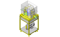
Assembly data shows the assembly drawings in the concept design phase. The sole purpose of the data is to explain the structure and functionality of the assembly and is not considered nor to be used as a final design.
You will need to edit the Data so that it meets your specific design conditions. -
Unit assembly Data consists of some sub-assemblies.
It is configured so that each sub-assembly unit can be used as it is or edited. - The Data for fabricated parts is based on easy-to-edit dimensions and shapes in sketches and histories.
- The Data including the third-part components are made by the Company.
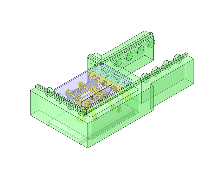
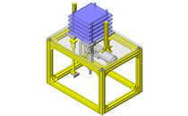
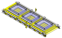
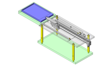
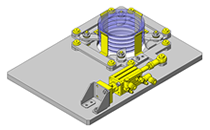
* The part in the frame is a sub-assembly unit.
-

- * Unit assembly Data consists of some sub-assemblies.
It is configured so that each sub-assembly unit can be used as it is or edited.
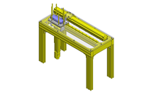
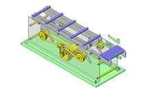
Application Overview
Purpose
- Purpose
- To transfer pallet at 90-degree angle from one conveyor to another.
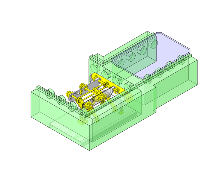
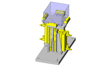
- Operation
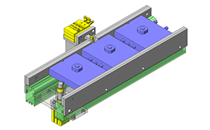
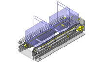
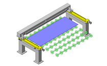
- At the transfer position, bellow the conveying height, is the lifting and transfer mechanism. When a pallet is in the transfer position the cylinder moves the unit and lifts the workpiece from conveyor. To make 90-degree transfer drive roller pulls the workpiece onto the next station. Besides drive roller (motor powered) workpiece is also supported by 3 sets of free-wheeling rollers as part of the lift and transfer unit. When the pallet leaves, the transfer unit cylinders retract and transfer unit is once again below the conveying height.
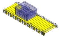
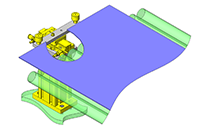
Target workpiece
- Pallet
- Size:W450×D300×H10mm
- Weight:3.7kg
- Load capacity:8kg
Design Specifications
Operating Conditions or Design Requirements
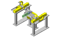
- Operational Specifications
- To conduct right angle transfer of pallets smoothly and prevent the conveyor rollers from being damaged, the transfer action should be started after the pallet is lifted.
- Transfer speed: 12 to 14 (m/min)
- Dimensions
- W500×D300×H250mm
Selection Criteria for Main Components
- A cylinder is selected based on the pallet and load capacity.
- A motor roller is selected based on load capacity.
- The drive roller diameter is selected based on needed transfer speed.
Design Evaluation
Verification of main components
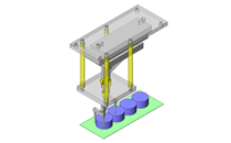
- A motor roller and a cylinder is selected based on the workpiece load.
- Conditional value: spring constant k = 9.8N/mm, spring free length X0 = 65mm, spring length when roller makes contact X1 = 47.2mm, distance between roller base rotation shaft and spring part Lk1 = 83mm, distance between roller base and roller contact point Lk2 = 158mm, air cylinder thrust at 0.5 MPa Fs0 = 402N, cylinder efficiency η = 0.8, cylinder thrust angle θ1 = 36°, distance between cylinder link rotation shaft and cylinder thrust point Ls1 = 150mm, distance between cylinder link and roller contact point Ls2 = 140.6mm, angle formed by motor roller shaft and drive roller shaft θ2 = 30.4°, angle formed by cylinder link and cylinder thrust direction θ3 ≈ 90°, motor roller strength Fm = 490N, motor roller diameter D1 = 42.7mm, drive roller diameter D2 = 40mm, motor roller speed V1 = 12.7m/min, friction coefficient between drive roller and pallet μ1 = 0.1, friction coefficient between motor roller and drive roller μ2 = 0.6 (metal and rubber), rated tangential force of motor roller N1 = 14.2N, workpiece weight M = 3.7 + 8 = 11.7kg, gravitational acceleration g = 9.8m/s²
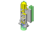
- Selection of motor roller
- Drive roller strength
[Force by spring]
If we put Fk1N as spring force and Fk2N as the force applied to the roller contact point, from the balance of moment around the roller base rotation shaft,
Fk1×Lk1=Fk2×Lk2
Fk2={k×(X0-X1)}×Lk1/Lk2={9.8×(65-47.2)}×83/158=91.6N
Therefore, the force in the normal direction applied by the spring to the roller contact face:Fk=Fk2×cosθ2=91.6×cos30.4=79N
[Force by cylinder]
If we put Fs1 as cylinder thrust and Fs2 as force applied to the roller contact point by the cylinder, from θ3 ≈ 90° and the balance of moment around the cylinder link rotation shaft,
Fs1×Ls1=Fs2×Ls2
Fs2={P0×η}×Ls1/Ls2={402×0.8}×150/140.6=343.1N
Angle formed by the cylinder thrust direction, drive roller shaft, and motor roller shaft:θ4=θ1+θ2=66.4°
Therefore, the force in the normal direction applied to the roller contact face by the cylinder:Fs=Fs2×cosθ4=343.1×cos66.4=137.4N
[Confirmation of roller strength]
From Fs > Fk, push force to motor roller:F=Fk=79N<490N=Fm
⇒As Fm > Fk, the condition is met. - Transfer Speed
As the roller is placed in between, considering the roller ratio,
transfer speed: V2 = V1 x D1/D2 = 12.7 x 42.7/40 = 13.5m/min, hence, the condition (12 to 14m/min) is met. - Pull force of drive motor
Maximum transmission force of motor roller and drive roller: P = F x μ2 = 79 x 0.6 = 47.4N
As N1 < P, the tangential force of the motor roller is transmitted to the drive roller without loss.
[Roller transfer capability]
Required tangential force of drive roller: N2 = 9.8 x M x μ1 = 9.8 x 11.7 x 0.1 = 11.5N
Considering the roller ratio, the required tangential force of the motor roller: N3 = N2 x D1/D2 = 11.5 x 43.7/40 = 12.3N < 14.2N = N1
⇒As N1 > N3, the condition is met.
- Drive roller strength
- Selection of air cylinder
- Confirmation of lift cylinder thrust
As links are used in this mechanism,
Lifting power: Fu = Fs0 x η x sinθ1 = 402 x 0.8 x sin36° = 189N
Workpiece weight:M×g=114.7N<189N=Fu
⇒The condition is met.
- Confirmation of lift cylinder thrust
Other Design Consideration
- Air cylinder and links allows lift unit to fully engage the pallet and allows drive roller to stay in contact with pallet during transfer.
- Although this mechanism is designed assuming the transfer conveyor height as 200 mm, an arrangement with a lower design height is also possible.
- Movement in the direction opposite to this setting is also possible.
Explore Similar Application Examples

-
-

-

-

-
-
-

-

-
-

-

-

-

-
-

-

-
-

-

-

-

Relevant category
-
-
-

-

-

-

-

-

-

-

-

-

-

-

-

-
-

-

-
-

-

-

-

-

-

-

-
-

-
-
-

-

-
-

-

-
-

-

-

Relevant category
-
-
-

-

-

-

-

-
-

-

-

-
-

-

-

-

-

-

-
-
-

-

-
-

-

-
-

-

-

-

-

-

-
-
-
-

-

-

-

-
-

-
-
-

-

-

-

-

-

-

-

-

-

-

-
-

-

-
-

-

-

-
-

-

-

-