(!)Due to Microsoft's end of support for Internet Explorer 11 on 15/06/2022, this site does not support the recommended environment.
Mon. - Fri. 8 a.m. - 6 p.m.
All Categories
-
Automation Components
Automation Components
Show all categories of Automation Components-
Linear Motion
-
Rotary Motion
-
Connecting Parts
-
Rotary Power Transmission
-
Motors
-
Conveyors & Material Handling
-
Locating, Positioning, Jigs & Fixtures
-
Inspection
-
Sensors, Switches
-
Pneumatics, Hydraulics
-
Vacuum Components
-
Hydraulic Equipment
-
Spray Equipment And Accessories
-
Pipe, Tubes, Hoses & Fittings
-
Modules, Units
-
Heaters, Temperature Control
-
Aluminum Extrusions, Framing, Support & Posts
-
Casters, Leveling Mounts, Posts
-
Doors, Cabinet Hardware
-
Springs, Shock Absorbers
-
Adjustment/Fastening Components, Pins, Magnets
-
Antivibration, Soundproofing Materials, Safety Products
-
- Fasteners
- Materials
-
Wiring Components
Wiring Components
Show all categories of Wiring Components-
LAN Cables / Industrial Network Cables
-
Equipment Specific Cables
-
Cordsets
-
Computer & AV Cables
-
Wire/Cable
-
Connector (General Purpose)
-
Crimp Terminal Components
-
Cable Organization
-
Cable Gland Components
-
Cable Bushing/Clip/Sticker
-
Screw/Spacer
-
Cable accessories
-
Tube
-
Electrical Conduits
-
Duct/Wiring
-
Electrical Wiring Tools
-
Dedicated tools
-
Soldering supplies
-
- Electrical & Controls
-
Cutting Tools
Cutting Tools
Show all categories of Cutting Tools-
Carbide End Mill
-
HSS End Mill
-
Concrete Drill Bits
-
Milling Cutter Insert / Holder
-
Core Drill Bits
-
Customized Straight Blade End Mill
-
Dedicated Cutter
-
Crinkey Cutters
-
Turning Tool
-
Drill
-
Cutting Tool Accessories
-
Screw Hole Related Tools
-
Reamer
-
Electric Drill Bits
-
Chamfering, Centering Tool
-
Hole Saws
-
Magnetic Drill Press Cutters
-
Step Drills
-
Wood Drills & Cutters
-
-
Processing Tools
- Packing & Logistics Storage Supplies
- Safety Products
-
Research and Development & Cleanroom Supplies
Research and Development & Cleanroom Supplies
Show all categories of Research and Development & Cleanroom Supplies - Press Die Components
-
Plastic Mold Components
Plastic Mold Components
Show all categories of Plastic Mold Components-
Ejector Pins
-
Sleeves, Center Pins
-
Core Pins
-
Sprue bushings, Gates, and other components
-
Date Mark Inserts, Recycle Mark Inserts, Pins with Gas Vent
-
Undercut, Plates
-
Leader Components, Components for Ejector Space
-
Mold Opening Controllers
-
Cooling or Heating Components
-
Accessories, Others
-
Components of Large Mold, Die Casting
-
-
Injection Molding Components
Injection Molding Components
Show all categories of Injection Molding Components-
Purging Agent
-
Injection Molding Machine Products
-
Accessories of Equipment
-
Auxiliary Equipment
-
Air Nippers
-
Air Cylinders
-
Air Chuck for Runner
-
Chuck Board Components
-
Frames
-
Suction Components
-
Parallel Air Chuck
-
Special Air Chuck
-
Mold Maintenance
-
Heating Items
-
Heat Insulation Sheets
-
Couplers, Plugs, One-touch Joints
-
Tubes, Hoses, Peripheral Components
-
- Webcode Seach | Series
-
#CODE
- Discontinued Products
Loading...
- inCAD Library Home
- > No.000265 Simplified Clamping Jig
No.000265 Simplified Clamping Jig
Spring loaded jig for manual operation.
Relevant category
- * Unit assembly Data consists of some sub-assemblies.
It is configured so that each sub-assembly unit can be used as it is or edited.
Application Overview
Purpose
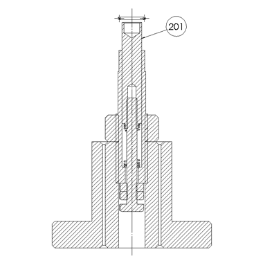
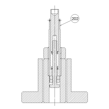
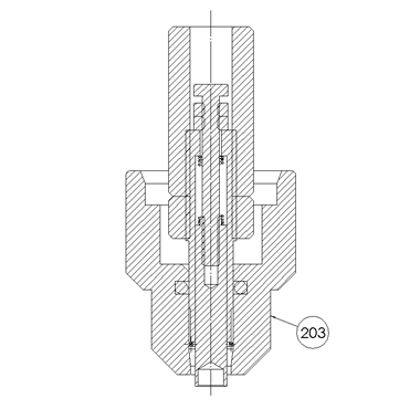
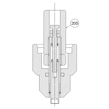
- The device in this application example consists of the insertion jig body (right side of figure) and the stand (left side of figure).
- O-ring setting
With the outermost sleeve of the jig body removed, set up the jig body in an opposite orientation to that shown in the figure on the left in the stand. The pin in the center has a dual structure. Set the workpiece (O-ring) on the inner pin and fit the removed outer sleeve back on. - Insertion positioning
Orient the center pin fit with the O-ring downward (state shown in the figure on the left) and butt the jig against the insertion position of the assembly counterpart (green). Also butt the end of the outer sleeve against the assembly counterpart. - Insertion of O-ring
When the cylindrical part shown at the center in the figure on the left is pressed with the hand, the outer part of the dual structure pin at the center slides and pushes the O-ring out. In the jig, a cylindrical nut is located below the cylindrical part and the push stroke is adjusted according to the nut position. When the hand is released, the cylindrical part at the center returns to the original position due to the reaction force of the compression spring that is installed between the pin parts in the dual structure.
Points for use
- Manual Operation
Applied to a portion where it is not possible to accurately incorporate an O-ring using your hands.
Target workpiece
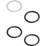
- Shape: O-ring (rubber)
- Size: inner diameter φ3 x t0.5mm
Design Specifications
Operating Conditions or Design Requirements
- Insertion stroke: 7mm
- Outer dimensions: φ20 x H42mm
Required Performance
- Positioning accuracy: ±0.2mm
- Assumed load: 0.75N
Selection Criteria for Main Components
- The O-ring insertion guide is made of MC nylon.
- The insertion pin is made of 304 Stainless Steel and precisely finished.
Design Evaluation
Verification of main components
- Confirmation of load of used spring
- Weight of parts to be returned: M = 14g
Friction coefficient between O-ring and pusher pin: f1 = 40g
Friction coefficient between inner guide and pusher pin: f2 = 10g
Required spring load: F
=M+f1+f2
=14+40+10
=65g
Spring constant: K = 10g/mm
Free length: 20mm
Set length: 8.2mm
Spring set load: P = 10 x (20 - 8.2)
= 10 x 11.8
≒120g
Therefore, P > F.
- Weight of parts to be returned: M = 14g
Other Design Consideration
- The dimensions of the jig part are determined by knowing the accuracy of the product using the O-ring.
- Friction is reduced at the O-ring insertion guide.
Explore Similar Application Examples
-
Relevant category


