(!)Due to Microsoft's end of support for Internet Explorer 11 on 15/06/2022, this site does not support the recommended environment.

ideanote
inCAD Library

Please read before use

What is inCAD Library?

  • Helpful application examples for mechanical engineers.

The Concept of inCAD Library

  • Online application library with a range of ideas for all manufacturing industries.
  • Save design time and learn new design applications when you are concepting new machines.

Disclaimer

  • MISUMI may not offer all parts in each application design. Available parts can only be purchased separately not as a unit shown in each application design.
  • MISUMI does not guarantee quality, accuracy, functionality, safety or reliability for the combination of the parts in each application example. Accept these points prior to use.
  • 2014 Copyright MISUMI
  • The data cannot be used for any purposes (including sales promotion) except for designing your machine.
  • All associated CAD is free. Misumi reserves the right at its sole discretion to cancel, terminate or modify this offer.
  • MISUMI may change, add or delete application examples posted without prior notice.
  • MISUMI assumes no responsibilities for any damage incurred resulting from your use of the Service or any change, addition or deletion by MISUMI of the application examples for any reason whatsoever.

inCAD Library Features

  1. Get great new design ideas for these application examples.
  2. Over 300 design application ideas
    collected from dozens of industries!

  3. Find application examples quickly! Search by function, workpiece shape, etc.

  4. Download the CAD models for each application example.
  5. Log in to download free CAD models.
    Download CAD for the entire application example!

Good IDEA! button

Click the Good IDEA! Button when you like an application example!

*Can only be clicked once per application example.

  • Upper right corner on the page of application example details

  • Pop-up dialog for CAD data downloading

Page top

Keyword Search
No. Search
SNS: 

No.000079 Grip Mechanism

Linkage operated grip mechanism controlled and released by an external force.

Relevant category

Single Axis Robot

Product name Single Axis Robot RSH1
Part number RSH120-C22A-C-F0-3-800
* Orange colored cells in the table below indicate the part numbers used in this example.

Selection criteria

Suitable for transferring workpieces in cycle time

Back to page top

Available sizes

Single Axis Robot (Straight)

Height
(mm)
Type Lead
(mm)
Stroke
(50 mm Increments)
65 RSH1 6 150-800
12
20
RSH2 5 150-1050
10
20
30
RSH3 5 150-1050
10
20

Back to page top

Selection steps

■Single Axis Robot Selection Steps

Load Capacity

Stroke

Cycle Time or Max. Speed

Check for Details

Back to page top

Accuracy Info

Accuracy of Single Axis Robot

Height
(mm)
Type Lead
(mm)
Stroke
(50 mm Increments)
Positioning Repeatability (mm)
65 RSH1 6 150-800 ±0.02
12
20
RSH2 5 150-1050 ±0.01
10
20
30
RSH3 5 150-1050 ±0.01
10
20

Back to page top

Performance info.

■Single axis robot Performance info.

Type Lead
(mm)
Max. load capacity(kg) Moment capacity (N·m) Max. speed(mm/sec)
Horizontal Vertical Pitching Yawing Rolling 150-550 600 650 700 750 800
RSH1 6 40 8 95 70 110 360 324 270 234 216 180
12 20 4 720 648 540 468 432 360
20 12 - 1200 1080 900 780 720 600
Type Lead
(mm)
Max. load capacity(kg) Moment capacity (N·m) Max. speed(mm/sec)
Horizontal Vertical Pitching Yawing Rolling 150-650 700 750 800 850 900 950 1000 1050
RSH2 5 50 16 95 70 110 300 255 225 195 180 165 150 135 120
10 40 8 600 510 450 390 360 330 300 270 240
20 20 4 1200 1020 900 780 720 660 600 540 480
30 7 - 1800 1530 1350 1170 1080 990 900 810 720
Type Lead
(mm)
Max. load capacity(kg) Moment capacity (N·m) Max. speed(mm/sec)
Horizontal Pitching Yawing Rolling 150-600 650 700 750 800 850 900 950 1000 1050
RSH3 5 80 163 128 143 300 255 225 195 180 165 150 135 120 105
10 60 600 510 450 390 360 330 300 270 240 210
20 30 1200 1020 900 780 720 660 600 540 480 420

Back to page top

Technical calculations

■ Single Axis Robot Technical Calculations

Selection Method of Single Axis Robot

Back to page top

Cantilever Shafts

Product name Cantilever Shafts - Flanged - with Tapped End
Part number FXEB6-12-F5-M3
* Orange colored cells in the table below indicate the part numbers used in this example.

Selection criteria

Pivot pin for link mechanism.

Back to page top

Available sizes

■Cantilever Shafts (Screw Mounted)

Type Material Surface Treatment
Round Type

Compact Type
1045 Carbon Steel Black Oxide
Electroless Nickel Plating
304 Stainless Steel -
Pin Dia.
(mm)
Pin Length
(1 mm Increments)
6 5-100
8
10
12 10-150
13
15
16
17
18
20
22
25
30
35
40
50

Back to page top

Accuracy Info

Accuracy of Cantilever Shafts

Perpendicularity: 0.02

Pin Dia.
(mm)
Tolerance g6
(mm)
6 -0.004
-0.012
8 -0.005
-0.014
10
12 -0.006
-0.017
13
15
16
17
18
20 -0.007
-0.020
22
25
30
35 -0.009
-0.025
40
50

Back to page top

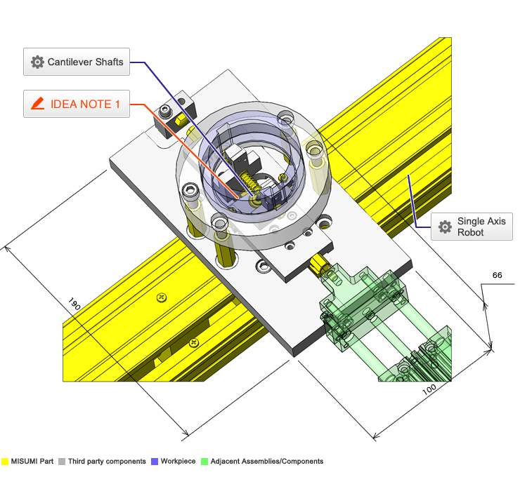
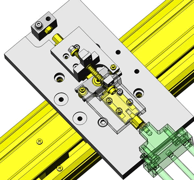
IDEA NOTE Workpiece retaining using a linkage mechanism.

Workpiece I.D. is Unrestrained and be released from one side by a linkage mechanism.

  • TERMS AND CONDITIONS FOR USE OF CAD DATA
    Your access to the CAD data that MISUMI Corporation (hereinafter referred to as the Company) posts on this site (including 3D CAD data, intermediate 3D CAD data and 2D CAD data; hereinafter referred to as the Data) are of products manufactured and/or sold by the Company (hereinafter referred to as the Products) assumes that you have read and accepted these terms and conditions which govern your use of the Data. If you do not agree to these terms and conditions, you must stop using this website and the Data. You must not use the Data for any unlawful purpose or in any manner inconsistent with these terms and conditions.
    1. CAD Data
    The Data is prepared for assisting the Company's users in the CAD design process by providing dimensions and other Product information. In order to provide the best speed and stability working within this site, the Product drawings were simplified to reduce the size of the Data. For instance, some of the Products are shown without the oil groove shape, screws or spring shape. Also, please be aware that the tolerance, surface roughness and/or chamfer of the Data may vary from the actual Products.
    2. Disclaimer on Data
    While the Company has carefully prepared the Data, accuracy of the Data is not guaranteed and is subject to the variances as described above. The Company may also modify, add or delete the Data at any time without prior notice. The Company assumes no liability for any direct, indirect, consequential or special damages that you may claim resulted from your use of the Data or any changes to or deletions of the Data regardless of the reason. The Company provides no warranty as to the quality, accuracy, functionality, safety or reliability of the combination of Products and parts. Example applications and combinations of the Products are provided for illustrative purposes only.
    3. Copyright
    Copyrights to the content and the Data belong to the Company or the manufacturers of the Products. The said copyright is protected by the Copyright Act and international treaties. The use (including duplication, modification, uploading, posting, transmission, distribution, licensing, sales and publishing) of the Data except for the purpose to use the Data described above without prior approval of the Company is not allowed. The Data cannot be used for any purposes (including sales promotion) except for designing your machine. If you violate this provision or the laws or regulations, the Company may prohibit you from the use of the Data, the Company’s site and/or take legal action. So long as you comply with these terms and conditions, the Company grants to you a non-exclusive, non-transferable, revocable license to access and use the Data for the sole purpose of assisting you in designing machines that incorporate products.
    In case that the CAD data is found to have been to be used for any purpose other than mentioned above or against the related laws, MISUMI may take legal actions, including the one for blocking the involved user from using CAD data and from accessing to the MISUMI site.
    4. Disclaimer of Warranty
    ANY AND ALL CONTENT APPEARING ON THIS WEB SITE IS PROVIDED FOR INFORMATIONAL PURPOSES ONLY. THIS WEB SITE, ITS CONTENT AND ITS LINKS ARE PROVIDED ON AN "AS IS" AND "AS AVAILABLE" BASIS AND ARE USED ONLY AT YOUR SOLE RISK, TO THE FULLEST EXTENT PERMISSIBLE BY LAW. THE COMPANY DISCLAIMS ALL WARRANTIES, EXPRESS OR IMPLIED, OF ANY KIND, REGARDING THIS WEB SITE (INCLUDING ITS CONTENT, HARDWARE, SOFTWARE AND LINKS), INCLUDING AS TO FITNESS FOR A PARTICULAR PURPOSE, MERCHANTABILITY, TITLE, NON INFRINGEMENT, RESULTS, ACCURACY, COMPLETENESS, ACCESSIBILITY, COMPATIBILITY, SECURITY AND FREEDOM FROM COMPUTER VIRUS. THE COMPANY WILL NOT BE LIABLE FOR ANY DAMAGES OR LOSSES, INCLUDING DIRECT, INDIRECT, CONSEQUENTIAL, SPECIAL, INCIDENTAL OR PUNITIVE DAMAGES AND/OR LOST PROFITS, IN CONNECTION WITH USE OF THE INTERNET, THIS WEB SITE, ITS CONTENT OR ITS LINKS
    Further, the Company will not be liable to you for any failure or delay by the Company to provide access to the Data or any of its obligations under these terms and conditions where such failure or delay is the direct or indirect result of any circumstances beyond the Company's reasonable control (and the Company's obligations will be suspended for the duration of such circumstances).
    5. Policy of Third Parties
    You may be required to separately agree to third party's policies if you use third party software to create or browse the Data or use a third party’s CAD data. In this case, the Company does not assume any responsibility for defects of such CAD data or the software of the third party or violation of their rights. Understand them before use.

    CAD Download (Unit Assembly)

    CAD Download: File Format
    生成

    Thank you for downloading the data.

    Click the Good IDEA! button when you find interesting design tips.


    This data is utilized in order to list more useful application examples in the future.

    CAD Data Limitations

    1. Assembly data shows the assembly drawings in the concept design phase. The sole purpose of the data is to explain the structure and functionality of the assembly and is not considered nor to be used as a final design.
      You will need to edit the Data so that it meets your specific design conditions.
    2. Unit assembly Data consists of some sub-assemblies.
      It is configured so that each sub-assembly unit can be used as it is or edited.
    3. * The part in the frame is a sub-assembly unit.

    4. The Data for fabricated parts is based on easy-to-edit dimensions and shapes in sketches and histories.
    5. The Data including the third-part components are made by the Company.

    Page top

  • * Unit assembly Data consists of some sub-assemblies.
       It is configured so that each sub-assembly unit can be used as it is or edited.

Application Overview

Purpose

  • Automated pusher mechanism for grip and release of molded plastic workpieces.

Points for use

  • Workpiece is gripped by jaws placed inside its bore diameter, roughly guided on its outer diameter, and is internally secured by a spring.
  • To release workpiece i.e. gripper jaws, external force is applied.

Target workpiece

  • Molded plastic product
    Dims.: φ67 x H30 mm
    Weight: 50g

Design Specifications

Operating Conditions or Design Requirements

  • External dims.: W190 x D100 x H66
  • Push stroke when clamped: 14mm
  • Single axis robot stroke: 800mm

Required Performance

  • Workpiece retaining load: 2.61N
  • Max. operating force when released: 6.67N

Selection Criteria for Main Components

  • Compression spring
    • Select a spring with a constant that does not apply excessive load on workpiece, as well as keeping the operation efforts low.
  • Linear guide
    • Since little moment loads apply, select an optimum guide relative to the fixture size.

Design Evaluation

Verification of main components

  • Verify retaining load during clamping and the pusher force when releasing.
  • Compression spring load
      • Reaction force F = kx
      • Workpiece retaining load: 2.61N
      • Assumed deflection when retaining workpiece: x = 9mm
      • From k = F / x = 2.61 / 0 = 0.29, spring constant k = 0.29N/mm is selected.

    • Assumed deflection when unchucked: x = 23mm (when workpiece retained 9mm (set length:36mm, free length: 45mm), when unchucked 14mm)
    • Spring load when unchucked: F = kx = 0.29 x 23 = 6.67N
    • Applied pressure by the pusher is 6.67N or more.

Explore Similar Application Examples

Page - / -

Part List

No. Part Name Sample Picture MISUMI Part Number
For Price and Days to ship click on Part No.
Quantity
1 Single-Axis Robot RSH1 RSH120-C22A-C-F0-3-800 1
2 Linear Guides SSELBZ10-55 2
3 Cantilever Pin FXEB6-12-F5-M3 1
4 Hex Posts PLSBWRK10-35 4
5 Ball Bearing B686ZZ 1
6 Metal Washers WSSB8-3-1 1
7 Metal Washers WSSB8-4-1 2
8 Cam Followers CFFA3-10 2
9 Flat Head Cap Screws FBAM4-65-20 1
10 Spring UR6-45 1
11 Soft Urethane UREWH10-4-2 2
12 Stop Pins STFHN8-10 2
13 Stop Pins BSTEH8 1
  • The part list above only contains MISUMI parts.
    Part list download (CSV) includes MISUMI and third party components used in this example.
  • TERMS AND CONDITIONS FOR USE OF CAD DATA
    Your access to the CAD data that MISUMI Corporation (hereinafter referred to as the Company) posts on this site (including 3D CAD data, intermediate 3D CAD data and 2D CAD data; hereinafter referred to as the Data) are of products manufactured and/or sold by the Company (hereinafter referred to as the Products) assumes that you have read and accepted these terms and conditions which govern your use of the Data. If you do not agree to these terms and conditions, you must stop using this website and the Data. You must not use the Data for any unlawful purpose or in any manner inconsistent with these terms and conditions.
    1. CAD Data
    The Data is prepared for assisting the Company's users in the CAD design process by providing dimensions and other Product information. In order to provide the best speed and stability working within this site, the Product drawings were simplified to reduce the size of the Data. For instance, some of the Products are shown without the oil groove shape, screws or spring shape. Also, please be aware that the tolerance, surface roughness and/or chamfer of the Data may vary from the actual Products.
    2. Disclaimer on Data
    While the Company has carefully prepared the Data, accuracy of the Data is not guaranteed and is subject to the variances as described above. The Company may also modify, add or delete the Data at any time without prior notice. The Company assumes no liability for any direct, indirect, consequential or special damages that you may claim resulted from your use of the Data or any changes to or deletions of the Data regardless of the reason. The Company provides no warranty as to the quality, accuracy, functionality, safety or reliability of the combination of Products and parts. Example applications and combinations of the Products are provided for illustrative purposes only.
    3. Copyright
    Copyrights to the content and the Data belong to the Company or the manufacturers of the Products. The said copyright is protected by the Copyright Act and international treaties. The use (including duplication, modification, uploading, posting, transmission, distribution, licensing, sales and publishing) of the Data except for the purpose to use the Data described above without prior approval of the Company is not allowed. The Data cannot be used for any purposes (including sales promotion) except for designing your machine. If you violate this provision or the laws or regulations, the Company may prohibit you from the use of the Data, the Company’s site and/or take legal action. So long as you comply with these terms and conditions, the Company grants to you a non-exclusive, non-transferable, revocable license to access and use the Data for the sole purpose of assisting you in designing machines that incorporate products.
    In case that the CAD data is found to have been to be used for any purpose other than mentioned above or against the related laws, MISUMI may take legal actions, including the one for blocking the involved user from using CAD data and from accessing to the MISUMI site.
    4. Disclaimer of Warranty
    ANY AND ALL CONTENT APPEARING ON THIS WEB SITE IS PROVIDED FOR INFORMATIONAL PURPOSES ONLY. THIS WEB SITE, ITS CONTENT AND ITS LINKS ARE PROVIDED ON AN "AS IS" AND "AS AVAILABLE" BASIS AND ARE USED ONLY AT YOUR SOLE RISK, TO THE FULLEST EXTENT PERMISSIBLE BY LAW. THE COMPANY DISCLAIMS ALL WARRANTIES, EXPRESS OR IMPLIED, OF ANY KIND, REGARDING THIS WEB SITE (INCLUDING ITS CONTENT, HARDWARE, SOFTWARE AND LINKS), INCLUDING AS TO FITNESS FOR A PARTICULAR PURPOSE, MERCHANTABILITY, TITLE, NON INFRINGEMENT, RESULTS, ACCURACY, COMPLETENESS, ACCESSIBILITY, COMPATIBILITY, SECURITY AND FREEDOM FROM COMPUTER VIRUS. THE COMPANY WILL NOT BE LIABLE FOR ANY DAMAGES OR LOSSES, INCLUDING DIRECT, INDIRECT, CONSEQUENTIAL, SPECIAL, INCIDENTAL OR PUNITIVE DAMAGES AND/OR LOST PROFITS, IN CONNECTION WITH USE OF THE INTERNET, THIS WEB SITE, ITS CONTENT OR ITS LINKS
    Further, the Company will not be liable to you for any failure or delay by the Company to provide access to the Data or any of its obligations under these terms and conditions where such failure or delay is the direct or indirect result of any circumstances beyond the Company's reasonable control (and the Company's obligations will be suspended for the duration of such circumstances).
    5. Policy of Third Parties
    You may be required to separately agree to third party's policies if you use third party software to create or browse the Data or use a third party’s CAD data. In this case, the Company does not assume any responsibility for defects of such CAD data or the software of the third party or violation of their rights. Understand them before use.

    CAD Download (Unit Assembly)

    CAD Download: File Format
    生成

    Thank you for downloading the data.

    Click the Good IDEA! button when you find interesting design tips.


    This data is utilized in order to list more useful application examples in the future.

    CAD Data Limitations

    1. Assembly data shows the assembly drawings in the concept design phase. The sole purpose of the data is to explain the structure and functionality of the assembly and is not considered nor to be used as a final design.
      You will need to edit the Data so that it meets your specific design conditions.
    2. Unit assembly Data consists of some sub-assemblies.
      It is configured so that each sub-assembly unit can be used as it is or edited.
    3. * The part in the frame is a sub-assembly unit.

    4. The Data for fabricated parts is based on easy-to-edit dimensions and shapes in sketches and histories.
    5. The Data including the third-part components are made by the Company.

    Page top

Page top