(!)Due to Microsoft's end of support for Internet Explorer 11 on 15/06/2022, this site does not support the recommended environment.
Mon. - Fri. 8 a.m. - 6 p.m.
All Categories
-
Automation Components
Automation Components
Show all categories of Automation Components-
Linear Motion
-
Rotary Motion
-
Connecting Parts
-
Rotary Power Transmission
-
Motors
-
Conveyors & Material Handling
-
Locating, Positioning, Jigs & Fixtures
-
Inspection
-
Sensors, Switches
-
Pneumatics, Hydraulics
-
Vacuum Components
-
Hydraulic Equipment
-
Spray Equipment And Accessories
-
Pipe, Tubes, Hoses & Fittings
-
Modules, Units
-
Heaters, Temperature Control
-
Aluminum Extrusions, Framing, Support & Posts
-
Casters, Leveling Mounts, Posts
-
Doors, Cabinet Hardware
-
Springs, Shock Absorbers
-
Adjustment/Fastening Components, Pins, Magnets
-
Antivibration, Soundproofing Materials, Safety Products
-
- Fasteners
- Materials
-
Wiring Components
Wiring Components
Show all categories of Wiring Components-
LAN Cables / Industrial Network Cables
-
Equipment Specific Cables
-
Cordsets
-
Computer & AV Cables
-
Wire/Cable
-
Connector (General Purpose)
-
Crimp Terminal Components
-
Cable Organization
-
Cable Gland Components
-
Cable Bushing/Clip/Sticker
-
Screw/Spacer
-
Cable accessories
-
Tube
-
Electrical Conduits
-
Duct/Wiring
-
Electrical Wiring Tools
-
Dedicated tools
-
Soldering supplies
-
- Electrical & Controls
-
Cutting Tools
Cutting Tools
Show all categories of Cutting Tools-
Carbide End Mill
-
HSS End Mill
-
Concrete Drill Bits
-
Milling Cutter Insert / Holder
-
Core Drill Bits
-
Customized Straight Blade End Mill
-
Dedicated Cutter
-
Crinkey Cutters
-
Turning Tool
-
Drill
-
Cutting Tool Accessories
-
Screw Hole Related Tools
-
Reamer
-
Electric Drill Bits
-
Chamfering, Centering Tool
-
Hole Saws
-
Magnetic Drill Press Cutters
-
Step Drills
-
Wood Drills & Cutters
-
-
Processing Tools
-
Packing & Logistics Storage Supplies
- Safety Products
-
Research and Development & Cleanroom Supplies
Research and Development & Cleanroom Supplies
Show all categories of Research and Development & Cleanroom Supplies - Press Die Components
-
Plastic Mold Components
Plastic Mold Components
Show all categories of Plastic Mold Components-
Ejector Pins
-
Sleeves, Center Pins
-
Core Pins
-
Sprue bushings, Gates, and other components
-
Date Mark Inserts, Recycle Mark Inserts, Pins with Gas Vent
-
Undercut, Plates
-
Leader Components, Components for Ejector Space
-
Mold Opening Controllers
-
Cooling or Heating Components
-
Accessories, Others
-
Components of Large Mold, Die Casting
-
-
Injection Molding Components
Injection Molding Components
Show all categories of Injection Molding Components-
Purging Agent
-
Injection Molding Machine Products
-
Accessories of Equipment
-
Auxiliary Equipment
-
Air Nippers
-
Air Cylinders
-
Air Chuck for Runner
-
Chuck Board Components
-
Frames
-
Suction Components
-
Parallel Air Chuck
-
Special Air Chuck
-
Mold Maintenance
-
Heating Items
-
Heat Insulation Sheets
-
Couplers, Plugs, One-touch Joints
-
Tubes, Hoses, Peripheral Components
-
- Webcode Seach | Series
-
#CODE
- Discontinued Products
Loading...
- inCAD Library Home
- > No.000150 90° Rotational Transfer Mechanism
No.000150 90° Rotational Transfer Mechanism
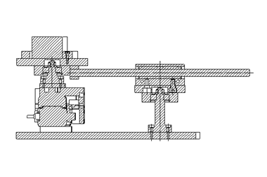
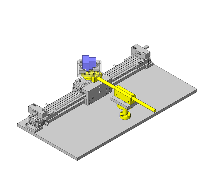
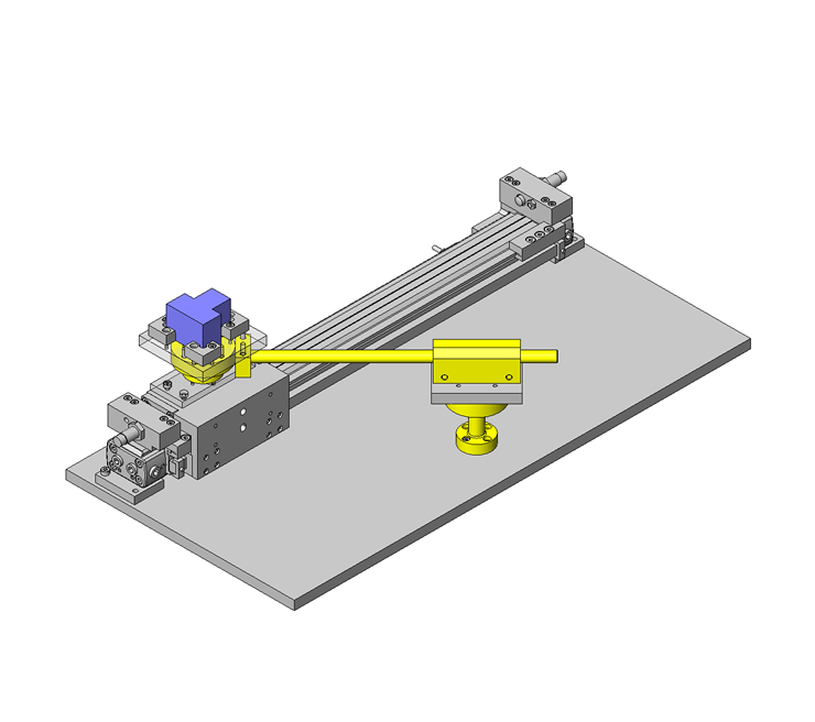
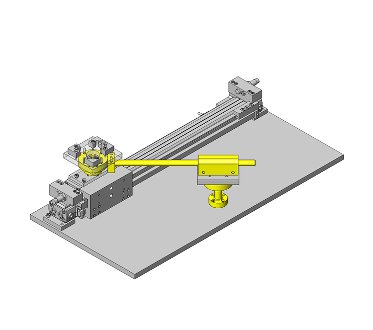
Rotate workpiece 90 degrees while transporting.
Relevant category
- * Unit assembly Data consists of some sub-assemblies.
It is configured so that each sub-assembly unit can be used as it is or edited.
Application Overview
Purpose
- Transfer and rotate a workpiece simultaneously.
Target workpiece
- Shape: Connector
- Size: W40 x D40 x H30 mm
- Weight: 150g
Design Specifications
Operating Conditions or Design Requirements
- Horizontal movement stroke: 300mm
- Rotation angle: 90°
- External dimensions: W500 x D250 x H123mm
Required Performance
- Positioning accuracy: ± 0.1/300mm
- Angle: 90° ± 0.05°
Selection Criteria for Main Components
- Ensure that the cylinder with shock absorbing stopper can provide the required positioning accuracy.
Design Evaluation
Verification of main components
- Verify that the cylinder thrust and shock absorber meet the design requirements.
- Conditional values: Friction coefficient of the guide on the rod-less cylinder μ= 0.01, air cylinder efficiency η = 0.82, mass of moving part = 1.6kg, workpiece mass = 150g
- φ 20 cylinder thrust: Fs = 157N at applied pressure of 0.5MPa
- Cylinder thrust necessary to transfer a workpiece F = (0.15 + 1.6) x 0.01 x 9.806/0.82 = 0.21N < 157N = Fs
⇒Sufficiently satisfied.
Check the shock absorber capacity. - Conditional values: Stroke of the shock absorber with these specifications St = 8mm, maximum absorbed energy Ea = 7J, Equivalent mass of the colliding object Me= 18kg [atV = 0.5 m/s]
- Check the absorbable kinetic energy.
E=1/2×m・V2+Fs×St=1/2×(0.15+1.6)×0.52+157×0.008=1.47J
Ea/2=7J/2=3.5>1.47J
⇒One half or less of the maximum absorbable energy. Thus the kinetic energy can be absorbed. - Check the absorbable equivalent mass of the colliding object.
Me=m+2・Fs・St/V2=(0.15+1.6)+2×157×0.008/0.52=6.774kg<Me=18kg
⇒Can be absorbed.
Other Design Consideration
- A cylinder with high mechanical rigidity is selected to meet the high positioning accuracy requirements.
Explore Similar Application Examples
-
Relevant category
-
Relevant category


