(!)Due to Microsoft's end of support for Internet Explorer 11 on 15/06/2022, this site does not support the recommended environment.
Mon. - Fri. 8 a.m. - 6 p.m.
All Categories
-
Automation Components
Automation Components
Show all categories of Automation Components-
Linear Motion
-
Rotary Motion
-
Connecting Parts
-
Rotary Power Transmission
-
Motors
-
Conveyors & Material Handling
-
Locating, Positioning, Jigs & Fixtures
-
Inspection
-
Sensors, Switches
-
Pneumatics, Hydraulics
-
Vacuum Components
-
Hydraulic Equipment
-
Spray Equipment And Accessories
-
Pipe, Tubes, Hoses & Fittings
-
Modules, Units
-
Heaters, Temperature Control
-
Aluminum Extrusions, Framing, Support & Posts
-
Casters, Leveling Mounts, Posts
-
Doors, Cabinet Hardware
-
Springs, Shock Absorbers
-
Adjustment/Fastening Components, Pins, Magnets
-
Antivibration, Soundproofing Materials, Safety Products
-
- Fasteners
- Materials
-
Wiring Components
Wiring Components
Show all categories of Wiring Components-
LAN Cables / Industrial Network Cables
-
Equipment Specific Cables
-
Cordsets
-
Computer & AV Cables
-
Wire/Cable
-
Connector (General Purpose)
-
Crimp Terminal Components
-
Cable Organization
-
Cable Gland Components
-
Cable Bushing/Clip/Sticker
-
Screw/Spacer
-
Cable accessories
-
Tube
-
Electrical Conduits
-
Duct/Wiring
-
Electrical Wiring Tools
-
Dedicated tools
-
Soldering supplies
-
- Electrical & Controls
-
Cutting Tools
Cutting Tools
Show all categories of Cutting Tools-
Carbide End Mill
-
HSS End Mill
-
Concrete Drill Bits
-
Milling Cutter Insert / Holder
-
Core Drill Bits
-
Customized Straight Blade End Mill
-
Dedicated Cutter
-
Crinkey Cutters
-
Turning Tool
-
Drill
-
Cutting Tool Accessories
-
Screw Hole Related Tools
-
Reamer
-
Electric Drill Bits
-
Chamfering, Centering Tool
-
Hole Saws
-
Magnetic Drill Press Cutters
-
Step Drills
-
Wood Drills & Cutters
-
-
Processing Tools
- Packing & Logistics Storage Supplies
- Safety Products
-
Research and Development & Cleanroom Supplies
Research and Development & Cleanroom Supplies
Show all categories of Research and Development & Cleanroom Supplies - Press Die Components
-
Plastic Mold Components
Plastic Mold Components
Show all categories of Plastic Mold Components-
Ejector Pins
-
Sleeves, Center Pins
-
Core Pins
-
Sprue bushings, Gates, and other components
-
Date Mark Inserts, Recycle Mark Inserts, Pins with Gas Vent
-
Undercut, Plates
-
Leader Components, Components for Ejector Space
-
Mold Opening Controllers
-
Cooling or Heating Components
-
Accessories, Others
-
Components of Large Mold, Die Casting
-
-
Injection Molding Components
Injection Molding Components
Show all categories of Injection Molding Components-
Purging Agent
-
Injection Molding Machine Products
-
Accessories of Equipment
-
Auxiliary Equipment
-
Air Nippers
-
Air Cylinders
-
Air Chuck for Runner
-
Chuck Board Components
-
Frames
-
Suction Components
-
Parallel Air Chuck
-
Special Air Chuck
-
Mold Maintenance
-
Heating Items
-
Heat Insulation Sheets
-
Couplers, Plugs, One-touch Joints
-
Tubes, Hoses, Peripheral Components
-
- Webcode Seach | Series
-
#CODE
- Discontinued Products
Loading...
- inCAD Library Home
- > No.000127 Workpiece Rotate and Transfer Mechanism
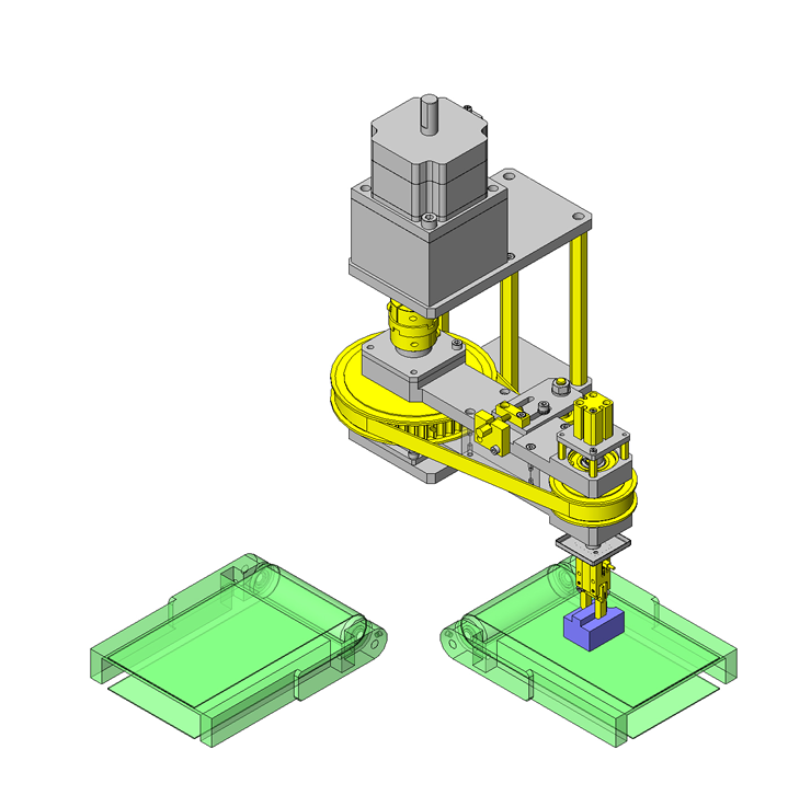
No.000127 Workpiece Rotate and Transfer Mechanism
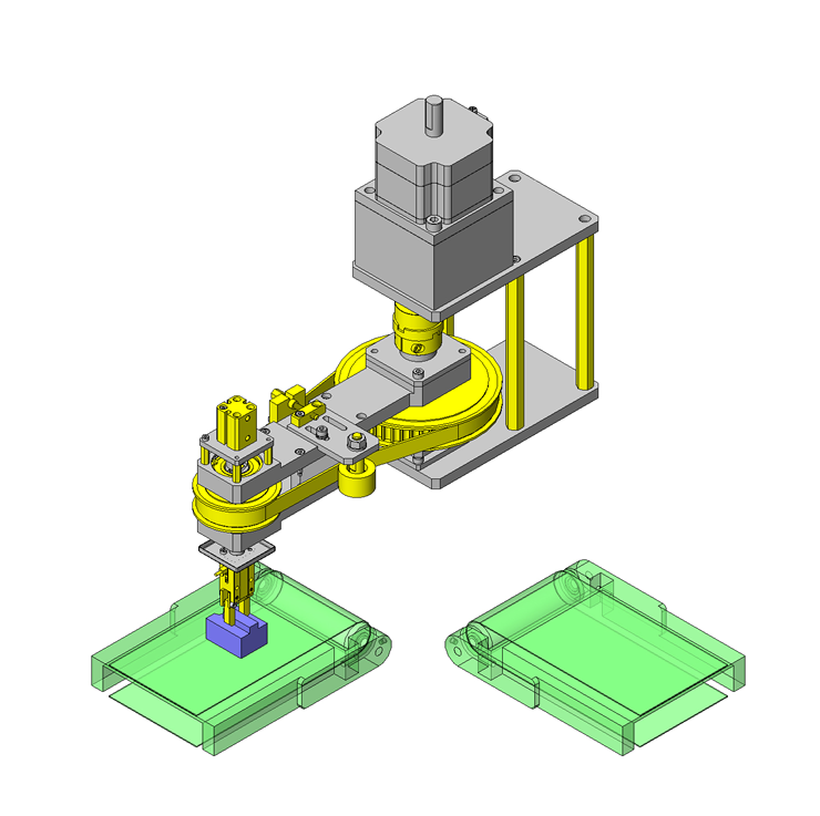
Rotate and transfer but workpiece orientation in direction of travel remains the same.
Relevant category
- * Unit assembly Data consists of some sub-assemblies.
It is configured so that each sub-assembly unit can be used as it is or edited.
Application Overview
Purpose
- (Purpose)
Workpieces on a conveyor are rotated 90 degrees and transferred to the next process.
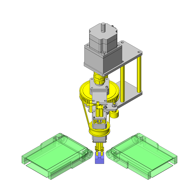
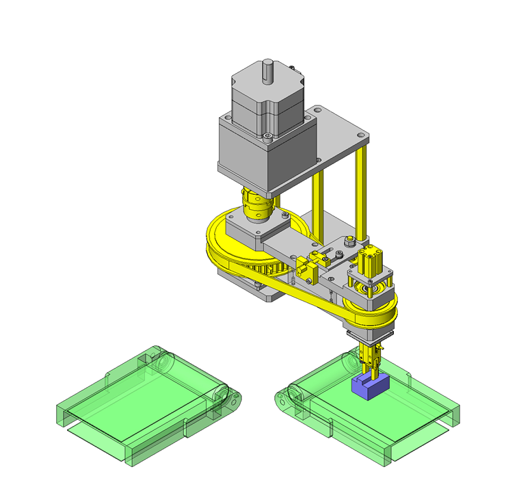
The gripper rotates 180 degrees, ensuring the workpiece is transferred without changing its orientation. - (Operation)
Gripper down → Grip workpiece → Gripper up → 90 degree rotation and transfer → Gripper rotate 180 degrees → Gripper down → Workpiece released → Gripper up
Target workpiece
- Shape: Connector
size: W40 x D30 x H26
Weight: 0.1kg
Design Specifications
Operating Conditions or Design Requirements
- Transfer angle: 90 degrees
- Rotation angle: 180 degrees
- Up/down cylinder stroke: 10mm
- Clamp stroke: 3mm One side
- External dims.: W136 (Before rotation) x D403 x H398
Selection Criteria for Main Components
- Timing pulley ratio is 2:1
- Minimize inertia by reducing weight of the swinging parts, etc.
- Select an air gripper force that accounts for the friction coefficient and the workpiece weight.
Design Evaluation
Verification of main components
- The Motor selection calculations are shown below since the inertia moment applied to the stepping motor is critical.
- Time for 90 degree motion t0: 0.5 sec.
- Acceleration time t1: 0.1 sec.
- Inertia moment of swinging object: JL = 4.16 × 10⁻²kg・m²
- Operation angle: θ=90°, Stepping motor min. step angle: θs=0.072°
- Operation pulse count: A=θ/θs=1250 pulses
- Pulse rate: f2 = A / (t0 - t1) = 3125Hz
- Motion speed: NM = θs / 360 × f2 × 60 = 37.5r/min
- Selected motor's rotor inertia moment: J0 = 1.1 x 10⁻⁴
- Gear ratio: I = 1/10
- Acceleration torque calculation: Ta = (J0・i² + JL) / 9.55 × NM / t1 = 2.065N・m
- Required torque calculation: TM = Ta x Safety margin = 4.13N・m (Safety margin of 2)
- Based on Motor Torque Characteristic chart, the selected motor is OK
- Confirmation of inertia ratio: JL/(J0×i²) = 3.78 ≦ 10 is OK
Other Design Consideration
- The pulley at the center of rotation is fixed.
- For actual installation, a cover will be needed to ensure safety and dust prevention.
Explore Similar Application Examples
-
Relevant category
-
Relevant category


