(!)Due to Microsoft's end of support for Internet Explorer 11 on 15/06/2022, this site does not support the recommended environment.
Mon. - Fri. 8 a.m. - 6 p.m.
All Categories
-
Automation Components
Automation Components
Show all categories of Automation Components-
Linear Motion
-
Rotary Motion
-
Connecting Parts
-
Rotary Power Transmission
-
Motors
-
Conveyors & Material Handling
-
Locating, Positioning, Jigs & Fixtures
-
Inspection
-
Sensors, Switches
-
Pneumatics, Hydraulics
-
Vacuum Components
-
Hydraulic Equipment
-
Spray Equipment And Accessories
-
Pipe, Tubes, Hoses & Fittings
-
Modules, Units
-
Heaters, Temperature Control
-
Aluminum Extrusions, Framing, Support & Posts
-
Casters, Leveling Mounts, Posts
-
Doors, Cabinet Hardware
-
Springs, Shock Absorbers
-
Adjustment/Fastening Components, Pins, Magnets
-
Antivibration, Soundproofing Materials, Safety Products
-
- Fasteners
- Materials
-
Wiring Components
Wiring Components
Show all categories of Wiring Components-
LAN Cables / Industrial Network Cables
-
Equipment Specific Cables
-
Cordsets
-
Computer & AV Cables
-
Wire/Cable
-
Connector (General Purpose)
-
Crimp Terminal Components
-
Cable Organization
-
Cable Gland Components
-
Cable Bushing/Clip/Sticker
-
Screw/Spacer
-
Cable accessories
-
Tube
-
Electrical Conduits
-
Duct/Wiring
-
Electrical Wiring Tools
-
Dedicated tools
-
Soldering supplies
-
- Electrical & Controls
-
Cutting Tools
Cutting Tools
Show all categories of Cutting Tools-
Carbide End Mill
-
HSS End Mill
-
Concrete Drill Bits
-
Milling Cutter Insert / Holder
-
Core Drill Bits
-
Customized Straight Blade End Mill
-
Dedicated Cutter
-
Crinkey Cutters
-
Turning Tool
-
Drill
-
Cutting Tool Accessories
-
Screw Hole Related Tools
-
Reamer
-
Electric Drill Bits
-
Chamfering, Centering Tool
-
Hole Saws
-
Magnetic Drill Press Cutters
-
Step Drills
-
Wood Drills & Cutters
-
-
Processing Tools
-
Packing & Logistics Storage Supplies
- Safety Products
-
Research and Development & Cleanroom Supplies
Research and Development & Cleanroom Supplies
Show all categories of Research and Development & Cleanroom Supplies - Press Die Components
-
Plastic Mold Components
Plastic Mold Components
Show all categories of Plastic Mold Components-
Ejector Pins
-
Sleeves, Center Pins
-
Core Pins
-
Sprue bushings, Gates, and other components
-
Date Mark Inserts, Recycle Mark Inserts, Pins with Gas Vent
-
Undercut, Plates
-
Leader Components, Components for Ejector Space
-
Mold Opening Controllers
-
Cooling or Heating Components
-
Accessories, Others
-
Components of Large Mold, Die Casting
-
-
Injection Molding Components
Injection Molding Components
Show all categories of Injection Molding Components-
Purging Agent
-
Injection Molding Machine Products
-
Accessories of Equipment
-
Auxiliary Equipment
-
Air Nippers
-
Air Cylinders
-
Air Chuck for Runner
-
Chuck Board Components
-
Frames
-
Suction Components
-
Parallel Air Chuck
-
Special Air Chuck
-
Mold Maintenance
-
Heating Items
-
Heat Insulation Sheets
-
Couplers, Plugs, One-touch Joints
-
Tubes, Hoses, Peripheral Components
-
- Webcode Seach | Series
-
#CODE
- Discontinued Products
Loading...
- inCAD Library Home
- > No.000175 Workpiece Gripper Unit with Suction Cups
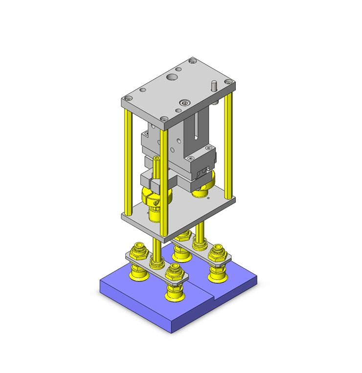
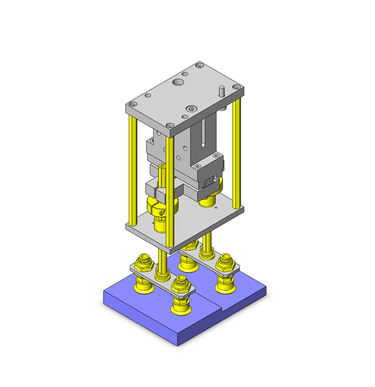
No.000175 Workpiece Gripper Unit with Suction Cups
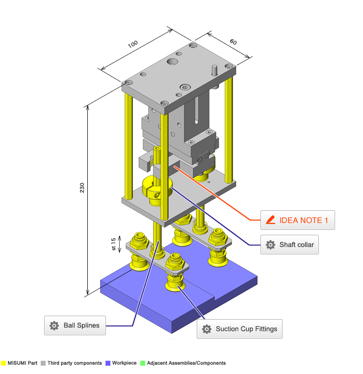
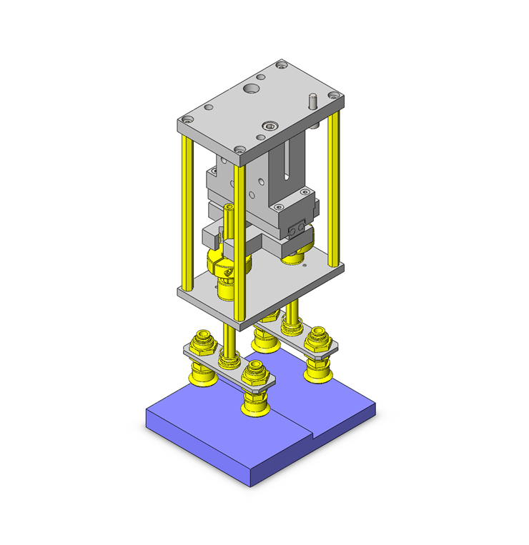
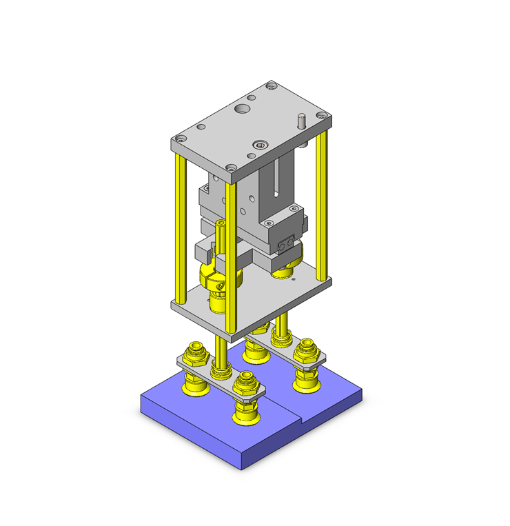
Fixing the sliding suction cup at hands.
Relevant category
- * Unit assembly Data consists of some sub-assemblies.
It is configured so that each sub-assembly unit can be used as it is or edited.
Application Overview
Purpose
- Purpose
- Using suction cups, various plastic work pieces with different step heights can be transported without changing the setup.
- Operation
- When work pieces vary, changing the suction cups is unnecessary. The suction cups unit slide up and down the spline shaft to absorb the different heights of the work pieces. Horizontal transportation of the work piece is conducted by fixing the upper part of the spline shaft with an air chuck.
Points for use
- Transportation of irregular shaped work pieces in their horizontal posture is possible by chucking the slide of the suction cup.
Target workpiece
- Shape: Plastic cases with height differences.
- Size: W 120 x D 100 x H 15 (allowable difference in step difference 10 mm)
- Weight: 800 g
Design Specifications
Operating Conditions or Design Requirements
- Suction cup stroke 15 mm
- Suction cup maximum reaction force: 7.93N x 2 (including weights of the guide, etc.)
- Hand gripping force: About 70N (air pressure 0.4MPa)
70×70%=49N - External size: W 100 x D 60 x H 230 mm
Required Performance
- Allowable transportable load: 8 N
Selection Criteria for Main Components
- Gripping force of the air chuck: >= 46.2N
Select an air chuck with a gripping force of 49 N.
Design Evaluation
Verification of main components
- Verify the transportable load limit by the air chuck for the feasibility of transporting the work pieces.
- Check the allowable transportable weight by air chuck gripping
- Conditional values: workpiece weight: M1 = 800g = 0.8kg, weight of a structure gripped by the air chuck: M2 = 0.4kg, gravitational acceleration g = 9.8 m/s², friction coefficient μ = 0.5 (rubber vs. metal), spring constant of the spring: k = 0.2 N/mm, maximum deflection of the spring: L = 21.5 mm, gripping force of the air chuck: H = 49 N
- Maximum downward load by the springs (2 pieces): S = k x L x 2 = 0.2 x 21.5 x 2 = 8.6N
- Downward load by the structure and springs: W = M2 x g + S = 0.4 x 9.8 + 8.6 = 3.9 + 8.6 = 12.5 N
- Maximum transportable weight with the chuck: P = H x μ = 49 x 0.5 = 24.5 N
Allowable transportable weight: Q = P - W = 24.5 - 12.5 = 12.0 N - Downward load of the workpiece: N = M1 x g = 0.8 x 9.8 = 7.8N This corresponds to 65% (=7.8/12×100) of the allowable transportable weight, and thus, the workpiece can be transported.
- Checking the allowable transportable weight of the suction cup
- Conditional values: Pad size = φ 20mm ∴ pressure receiving area S = 3.14cm², vacuum pressure P = - 80 kPa, safety factor t = 4
Sling up capacity: W [N] = P x S x 0.1/t= 80 x (3.14 x 4pieces) x 0.1/4 = 25.1N
⇒Allowable transportable weight of the air chuck 24.5N ≦ allowable transportable weight of the suction cup 25.1N Thus, the workpiece can be transported.
- Conditional values: Pad size = φ 20mm ∴ pressure receiving area S = 3.14cm², vacuum pressure P = - 80 kPa, safety factor t = 4
Other Design Consideration
- By sliding the suction cup up and down using the guide, irregular shaped work pieces can be transported.
The orientation of irregular shaped work pieces can be retained by holding and fixing the slide with a chuck. - Rubber pads are affixed on the inner sides of the chuck grips to retain the position of the spline shaft.
Explore Similar Application Examples
-
Relevant category
-
Relevant category


