(!)Due to Microsoft's end of support for Internet Explorer 11 on 15/06/2022, this site does not support the recommended environment.
Our Business Hours:
Mon. - Fri. 8 a.m. - 6 p.m.
Mon. - Fri. 8 a.m. - 6 p.m.
All Categories
Categories
- Automation Components
- Linear Motion
- Rotary Motion
- Connecting Parts
- Rotary Power Transmission
- Motors
- Conveyors & Material Handling
- Locating, Positioning, Jigs & Fixtures
- Inspection
- Sensors, Switches
- Pneumatics, Hydraulics
- Vacuum Components
- Hydraulic Equipment
- Spray Equipment And Accessories
- Pipe, Tubes, Hoses & Fittings
- Modules, Units
- Heaters, Temperature Control
- Aluminum Extrusions, Framing, Support & Posts
- Casters, Leveling Mounts, Posts
- Doors, Cabinet Hardware
- Springs, Shock Absorbers
- Adjustment/Fastening Components, Pins, Magnets
- Antivibration, Soundproofing Materials, Safety Products
- Fasteners
- Materials
- Wiring Components
- LAN Cables / Industrial Network Cables
- Equipment Specific Cables
- Cordsets
- Computer & AV Cables
- Wire/Cable
- Connector (General Purpose)
- Crimp Terminal Components
- Cable Organization
- Cable Gland Components
- Cable Bushing/Clip/Sticker
- Screw/Spacer
- Cable accessories
- Tube
- Electrical Conduits
- Duct/Wiring
- Electrical Wiring Tools
- Dedicated tools
- Soldering supplies
- Electrical & Controls
- Cutting Tools
- Carbide End Mill
- HSS End Mill
- Concrete Drill Bits
- Milling Cutter Insert / Holder
- Core Drill Bits
- Customized Straight Blade End Mill
- Dedicated Cutter
- Crinkey Cutters
- Turning Tool
- Drill
- Cutting Tool Accessories
- Screw Hole Related Tools
- Reamer
- Electric Drill Bits
- Chamfering, Centering Tool
- Hole Saws
- Magnetic Drill Press Cutters
- Step Drills
- Wood Drills & Cutters
- Processing Tools
- packing & logistics storage supplies
- Safety Products
- research and development & cleanroom supplies
- Press Die Components
- Plastic Mold Components
- Ejector Pins
- Sleeves, Center Pins
- Core Pins
- Sprue bushings, Gates, and other components
- Date Mark Inserts, Recycle Mark Inserts, Pins with Gas Vent
- Undercut, Plates
- Leader Components, Components for Ejector Space
- Mold Opening Controllers
- Cooling or Heating Components
- Accessories, Others
- Components of Large Mold, Die Casting
- Injection Molding Components
- Purging Agent
- Injection Molding Machine Products
- Accessories of Equipment
- Auxiliary Equipment
- Air Nippers
- Air Cylinders
- Air Chuck for Runner
- Chuck Board Components
- Frames
- Suction Components
- Parallel Air Chuck
- Special Air Chuck
- Mold Maintenance
- Heating Items
- Heat Insulation Sheets
- Couplers, Plugs, One-touch Joints
- Tubes, Hoses, Peripheral Components
Applications
Brands
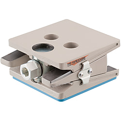
Leveling Legs - Wedge style, stabilizing, with or without pad.

Move the mouse over the image to zoom


- Volume Discount
- Lead Time Reduction
More precise leveling adjustment can be achieved with this leveling mount. Use it for leveling by installing onto the device.
- inCAD Components
Part Number
Configured Part Number is shown.

・Materials
| Type | Main Body | Adjusting Bolt | Stabilizer | Rubber | ||||
| [ M ]Material | [ S ]Surface Treatment | [ M ]Material | [ S ]Surface Treatment | [ M ]Material | [ S ]Surface Treatment | [ M ]Material (Color) | [ H ]Hardness | |
| KHWM-C | FCD Cast Iron | Baked Finish | 1045 Carbon Steel | Electrolytic Zinc Plating | - | - | - | - |
| KHWM-P | Nitrile Rubber (Blue) | Shore A95 | ||||||
| KHWM-SC | 1018 Carbon Steel | Electrolytic Zinc Plating | - | - | ||||
| KHWM-SP | Nitrile Rubber (Blue) | Shore A95 | ||||||
Specifications
| Part Number |
| KHWM-SC56 |
| Type | Part Number | A | C | H | h1 | h2 | Y | E | F | Adjusting Bolt Dimension | Stabilizer | Pad | Allowable Vertical Load (kN) | Height Adjustment (mm) | Level Accuracy (mm/rev.) | Incline Adjustment Angle | Mass (kg) | |||||
| Type | H | B | b | D | d | W | V | |||||||||||||||
| W/o Stabilizer | W/o Pad | KHWM-C | 47 | 110 | 115 | 47 | 41 | 53 | 20 | 64 | 51 | 22 | 12 | - | - | - | - | 50 | ±6 | 0.24 | - | 3.3 |
| 51 | 130 | 140 | 51 | 45 | 57 | 74 | 66 | 70 | 5.4 | |||||||||||||
| With Pad | KHWM-P | 52 | 110 | 115 | 52 | 46 | 58 | 64 | 51 | 111 | 106 | 16 | 3.4 | |||||||||
| 56 | 130 | 140 | 56 | 50 | 62 | 74 | 66 | 136 | 126 | 25 | 5.5 | |||||||||||
| With Stabilizer | W/o Pad | KHWM-SC | 56 | 110 | 115 | 56 | 50 | 62 | 20 | 64 | 51 | 22 | 12 | 108 | 78 | - | - | 50 | ±3° | 3.6 | ||
| 62 | 130 | 140 | 62 | 56 | 68 | 74 | 66 | 70 | 6.0 | |||||||||||||
| With Pad | KHWM-SP | 61 | 110 | 115 | 61 | 55 | 67 | 64 | 51 | 111 | 106 | 16 | 3.7 | |||||||||
| 67 | 130 | 140 | 67 | 61 | 73 | 74 | 66 | 136 | 126 | 25 | 6.1 | |||||||||||
■Rubber Pad Characteristics
[ ! ]Tests of tensile strength and elongation are conducted based on the JIS Standards K6251.
| Item | Unit | HDR Rubber |
| Hardness | Shore A | 95 |
| Specific Gravity | - | 1.25 |
| Tensile Strength | MPa | 6.5 |
| Elongation | % | 100 |
| Max. Operating Temperature | °C | 80 |
| Continuous Use Temperature | °C | 70 |
| Cold Resistance | °C | 0 |
■Bolt, Nut and Washer Selection Example
[ ! ]About Anchor Bolts
· AnchorCustomers are to provide the mounting bolts. Please provide M16 (Coarse).
· Length of anchor bolts ≥ device flange/frame thickness + depth of screwed-in leveling mount (total depth) + hex nut and plain washer thickness.
· Anchor bolt mounting holes can be ignored when not necessary.
| Part Number | How to Mount | Mounting Height H | Selected Bolt | |||
| Screw-In Depth (Overall Depth) | Base Thickness | Nut | Washer | |||
| LBNR16- | FWS16- | RCB16- | ||||
| Click here | Click here | Click here | ||||
| KHWM-P52 | Device Mounting | 53 | Arbitrary | 13 | 2.5 | RCB16- L Dimension |
| KHWM-P56 | 57 | |||||
| KHWM-SP61 | 62 | |||||
| KHWM-SP67 | 68 | |||||
| KHWM-C47 | 53 | |||||
| KHWM-C51 | 57 | |||||
| KHWM-SC56 | 62 | |||||
| KHWM-SC62 | 68 | |||||
· AnchorCustomers are to provide the mounting bolts. Please provide M16 (Coarse).
· Length of anchor bolts ≥ device flange/frame thickness + depth of screwed-in leveling mount (total depth) + hex nut and plain washer thickness.
· Anchor bolt mounting holes can be ignored when not necessary.
■Grease Characteristics
Feature: Achieves good lubricating performance in wide range of temperature from low to high.
| Name | Item | Contained Amount | Unit | Measurement Method | Conditions |
| Fluorinated Resin | Thickener | - | - | - | - |
| Per-Fluoro Polyether Oil | Base Oil | - | - | - | - |
| Dropping Point | None | - | JIS K-2220 5, 4 | - | |
| Evaporation Amount | ≤0.2 | mass% | Proprietary scheme | 200°C, 24h | |
| Oil Separation | ≤10 | mass% | Proprietary scheme | ||
| mass% | |||||
| mass% | |||||
| Device Mounting Example | Anchor Fixing Example | ||
 |  | ||
Part Number
CAD Data download and 3D preview are not available because the part number has not yet been determined.
- *In order to open the CAD Data download and 3D preview screen, the part number must be fixed.
- Please confirm the part number from "Specification / Dimension"on the left side, and then perform the CAD Data Download / 3D Preview operation.
Loading...
| Part Number |
|---|
| KHWM-C47 |
| KHWM-C51 |
| KHWM-P52 |
| KHWM-P56 |
| KHWM-SC56 |
| KHWM-SC62 |
| KHWM-SP61 |
| KHWM-SP67 |
| Part Number |
|---|
Loading...
More Information


■Feature
· This leveling mount enables installation and height adjustment of devices and apparatuses due to the effect of integrated special springs.
· Working efficiency is increased since the adjusting bolt head doesn't move back and forth when adjusted.
· Low particle generation fluorinated grease is applied to Standard Type, which is suitable for clean environments. (Clean Room Class is not guaranteed.)
· With Pad Type has an attenuation effect for self-induced vibration. Also excels in oil resistance and antitransitivity (color transfer to the floor).
· With Stabilizer Type is applicable to the floor inclination (±3°) to maintain the device horizontal, which ensures stable work environments.
■Leveling Adjustment Range
Please be sure to use within the leveling adjustment range (±6mm) as shown in the table above. 1mm clearance at part A should be remained for the minimum height. This clearance is to avoid interference between the slide groove and the slide fixing bracket. Note that if the level is lower, the casted main body will be in contact and the slide fixing bracket will come off from the slide groove, which will cause damage or breakage. For the maximum height, the tip of the middle part slides to the side edge of the upper/lower part for A130 and C140, while it slides to the edge of the leveling bolt for A110 and C115. Do not increase the height further.
Please be sure to use within the leveling adjustment range (±6mm) as shown in the table above. 1mm clearance at part A should be remained for the minimum height. This clearance is to avoid interference between the slide groove and the slide fixing bracket. Note that if the level is lower, the casted main body will be in contact and the slide fixing bracket will come off from the slide groove, which will cause damage or breakage. For the maximum height, the tip of the middle part slides to the side edge of the upper/lower part for A130 and C140, while it slides to the edge of the leveling bolt for A110 and C115. Do not increase the height further.
■ Major Application
· FPD Manufacturing Processor
· Semiconductor Manufacturing Processor
· Precision Metal Processor
· Large Precision Measuring Instrument
· Other Devices and Apparatuses
· FPD Manufacturing Processor
· Semiconductor Manufacturing Processor
· Precision Metal Processor
· Large Precision Measuring Instrument
· Other Devices and Apparatuses
■ How to Mount
①The flange, frame and the floor of the device on which leveling mounts are to be mounted require adequate rigidity.
②Place a device gently onto the leveling mount.
③When mounting a leveling mount on the device with bolts, align the mounting holes of the device and the tap position of the leveling mounts. Insert a hex bolt, a hex nut and a plain washer into a mounting hole of the device and screw them in the tap of the leveling mount. Do not tighten the hex nut at this point. (Hex bolts, hex nuts and plain washers are supplied by users.) After level ajustment 5 is complete, tighten hex nuts and plain washers. Please note that if the support load is very light, the leveling mount may slant due to the overtightening of nuts.
④Turn the hex head (hole) on the front side of the leveling mount by a tool and adjust the level of the device. Turn clockwise to increase the level and counterclockwise to decrease the level.
⑤Adjust each leveling mount gradually to avoid load concentration on the leveling mount.
■ Other Cautions
[ ! ]Jack up the device at a certain height previously, install the leveling mounts and make a final adjustment using the leveling mounts.
[ ! ]The middle part (wedge shape) moves back and forth when adjusting the level. Keep 30mm clearance in back of the leveling mounts.
[ ! ]Please pay close attention to safety measures.
- The specifications and dimensions of some parts may not be fully covered. For exact details, refer to manufacturer catalogs .
Additional Products in this Category
- Lifting Units - Light load, with machined bore option.
- Caster Wheels - with Internal Bearing
- Leveling Legs - Lift type, for medium loads, manual operation.
- Dedicated Caster H Series Wheel, Rubber Wheel for Heavy Loads H-RB (Gold Caster/GOLD CASTER)
- SW Rubber (for Use with Stainless Steel)
- U Urethane Foam (for Low-Floor with Heavy Loads)
- MC Monomer Casting Nylon (for Stainless Steel)
- TR-AW Type Aluminum Core Gold Type Wheel Only
Complementary Products


Tech Support
- Technical Support
- Tel:+52-442-672-7661 ext. 2 then wait and dial 4
E-mail: soportetecnico@misumimex.com - Mon. - Fri. 8 a.m. - 6 p.m.
- Technical Inquiry
How can we improve?
How can we improve?
While we are not able to respond directly to comments submitted in this form, the information will be reviewed for future improvement.
Customer Privacy Policy
Thank you for your cooperation.
While we are not able to respond directly to comments submitted in this form, the information will be reviewed for future improvement.
Please use the inquiry form.
Customer Privacy Policy