(!)Due to Microsoft's end of support for Internet Explorer 11 on 15/06/2022, this site does not support the recommended environment.
Our Business Hours:
Mon. - Fri. 8 a.m. - 6 p.m.
Mon. - Fri. 8 a.m. - 6 p.m.
All Categories
Categories
- Automation Components
- Linear Motion
- Rotary Motion
- Connecting Parts
- Rotary Power Transmission
- Motors
- Conveyors & Material Handling
- Locating, Positioning, Jigs & Fixtures
- Inspection
- Sensors, Switches
- Pneumatics, Hydraulics
- Vacuum Components
- Hydraulic Equipment
- Spray Equipment And Accessories
- Pipe, Tubes, Hoses & Fittings
- Modules, Units
- Heaters, Temperature Control
- Aluminum Extrusions, Framing, Support & Posts
- Casters, Leveling Mounts, Posts
- Doors, Cabinet Hardware
- Springs, Shock Absorbers
- Adjustment/Fastening Components, Pins, Magnets
- Antivibration, Soundproofing Materials, Safety Products
- Fasteners
- Materials
- Wiring Components
- LAN Cables / Industrial Network Cables
- Equipment Specific Cables
- Cordsets
- Computer & AV Cables
- Wire/Cable
- Connector (General Purpose)
- Crimp Terminal Components
- Cable Organization
- Cable Gland Components
- Cable Bushing/Clip/Sticker
- Screw/Spacer
- Cable accessories
- Tube
- Electrical Conduits
- Duct/Wiring
- Electrical Wiring Tools
- Dedicated tools
- Soldering supplies
- Electrical & Controls
- Cutting Tools
- Carbide End Mill
- HSS End Mill
- Concrete Drill Bits
- Milling Cutter Insert / Holder
- Core Drill Bits
- Customized Straight Blade End Mill
- Dedicated Cutter
- Crinkey Cutters
- Turning Tool
- Drill
- Cutting Tool Accessories
- Screw Hole Related Tools
- Reamer
- Electric Drill Bits
- Chamfering, Centering Tool
- Hole Saws
- Magnetic Drill Press Cutters
- Step Drills
- Wood Drills & Cutters
- Processing Tools
- packing & logistics storage supplies
- Safety Products
- research and development & cleanroom supplies
- Press Die Components
- Plastic Mold Components
- Ejector Pins
- Sleeves, Center Pins
- Core Pins
- Sprue bushings, Gates, and other components
- Date Mark Inserts, Recycle Mark Inserts, Pins with Gas Vent
- Undercut, Plates
- Leader Components, Components for Ejector Space
- Mold Opening Controllers
- Cooling or Heating Components
- Accessories, Others
- Components of Large Mold, Die Casting
- Injection Molding Components
- Purging Agent
- Injection Molding Machine Products
- Accessories of Equipment
- Auxiliary Equipment
- Air Nippers
- Air Cylinders
- Air Chuck for Runner
- Chuck Board Components
- Frames
- Suction Components
- Parallel Air Chuck
- Special Air Chuck
- Mold Maintenance
- Heating Items
- Heat Insulation Sheets
- Couplers, Plugs, One-touch Joints
- Tubes, Hoses, Peripheral Components
Applications
Brands
- Webcode Seach | Series
-
#CODE
- Discontinued Products
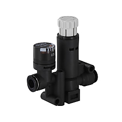
Regulators - In-Line with Gauge
Click this image to zoom it.
Move the mouse over the image to zoom
- Volume Discount
Regulator equipped with Pressure Gauge and capable of confirming the pressure.
- inCAD Components

Part Number
Configured Part Number is shown.


Specifications
| Part Number |
| RGUNP4 |
| Part Number | D1 | D2 | B | L1 | L2 | L3 | L4 | P1 | P2 | P3 | C1 | C2 | E1 | E2 | F1 | F2 | F3 | F4 | F5 | F6 | F7 | F8 | T1 | T2 | X1 | X2 | Y1 | Y2 | Mass (g) | ||
| Type | No. | Max | Min | ||||||||||||||||||||||||||||
| RGUNP | 4 | 4 | 4 | 61.6 | 59 | 43.3 | 13 | 18.8 | 1 | 11.5 | 11.5 | 15 | 11 | 11 | 21.6 | 30.6 | 15 | 30 | 4.2 | 17 | 10.1 | 20.2 | 10.2 | 9 | 24.5 | 15 | 9.8 | 9.8 | 7.8 | 7.8 | 23 |
| 6−4 | 6 | 11.6 | 22 | 11.8 | 9.8 | 9.8 | |||||||||||||||||||||||||
| 6 | 6 | 11.6 | 31 | 11.8 | 9.8 | ||||||||||||||||||||||||||
| 8−6 | 8 | 65.7 | 63.1 | 49.8 | 15 | 22.5 | - | 15.5 | 15.5 | 19 | 18.1 | 17 | 28.6 | 33 | 19.9 | 39.7 | 4.1 | 21.3 | 11.6 | 23.2 | 9.1 | 13 | 28.4 | 19 | - | - | - | - | 36 | ||
| 8 | 8 | 18.1 | 32.9 | ||||||||||||||||||||||||||||
Part Number
CAD Data download and 3D preview are not available because the part number has not yet been determined.
- *In order to open the CAD Data download and 3D preview screen, the part number must be fixed.
- Please confirm the part number from "Specification / Dimension"on the left side, and then perform the CAD Data Download / 3D Preview operation.
Loading...
| Part Number |
|---|
| RGUNP4 |
| RGUNP6 |
| RGUNP6-4 |
| RGUNP8 |
| RGUNP8-6 |
Loading...
More Information
■Precautions for Use
Do not use the regulator in such a way that the pressure exceeds the preset level due to large pressure fluctuations on the secondary side. This product is not designed as a relief valve, and using it as one may cause equipment damage or malfunction. If using it in this way, please install additional safety mechanisms.
Do not use the regulator in such a way that the pressure exceeds the preset level due to large pressure fluctuations on the secondary side. This product is not designed as a relief valve, and using it as one may cause equipment damage or malfunction. If using it in this way, please install additional safety mechanisms.
■Precautions for Use
1. Set the pressure by turning the regulating knob in the upward direction (clockwise). The pressure cannot be set accurately if the regulating knob is turned in the downward direction (counterclockwise).
2. Do not turn the regulating knob counterclockwise from a fully open position, or too far clockwise from a fully open position. Doing so may cause damage to the regulating knob or the regulator/valve itself. It can also increase the torque on the regulating screw and regulating knob.
3. The regulating knob releases when pulled up and locks when pushed down. Always lock the knob after adjusting the pressure. Failure to lock the regulating knob means the knob may turn, causing the pressure to change.
4. When you press down the regulating knob, it can sometimes stop partway between the locked and unlocked positions depending on how far round it is rotated. When this happens, the knob is not completely locked. Please ensure that the regulating knob is fully pushed down to the locked position.
5. Trying to force the regulating knob to turn while it is in the locked position may cause damage to the locking mechanism.
6. For models with a gauge, the gauge can be oriented in any direction. Applying excessive force to the gauge cap can result in damage to the gauge and cause issues with gauge readings. Please hold the gauge close to the base when turning it.
7. The pressure gauge is accurate to ±5% (FS). If greater accuracy is required, please check the pressure using a separate pressure gauge and adjust accordingly.
8. When air is released from the secondary side, the air flow may cause resonance. Avoid releasing air on the secondary side for prolonged periods of time, as this poses a risk of internal damage or other issues.
■Pressure Adjustment Method
1. Adjusting the pressure Release the lock by pulling the regulating knob upward before adjusting the pressure. Do not apply excessive force to the regulating knob during this time, as doing so may cause damage.
2. Increasing the pressure Turn the regulating knob clockwise from the fully open position to increase the pressure. When the desired pressure is reached, be sure to push the regulating knob down to lock it in place so that the pressure setting does not change.
3. Decreasing the pressure If the regulator knob is turned too far (if the pressure is too high), turning it counterclockwise will activate the relief mechanism and decrease the pressure. Following this, adjust as described in “2. Increasing the pressure.” When the desired pressure is reached, be sure to push the regulating knob down to lock it in place so that the pressure setting does not change.
1. Adjusting the pressure Release the lock by pulling the regulating knob upward before adjusting the pressure. Do not apply excessive force to the regulating knob during this time, as doing so may cause damage.

2. Increasing the pressure Turn the regulating knob clockwise from the fully open position to increase the pressure. When the desired pressure is reached, be sure to push the regulating knob down to lock it in place so that the pressure setting does not change.
3. Decreasing the pressure If the regulator knob is turned too far (if the pressure is too high), turning it counterclockwise will activate the relief mechanism and decrease the pressure. Following this, adjust as described in “2. Increasing the pressure.” When the desired pressure is reached, be sure to push the regulating knob down to lock it in place so that the pressure setting does not change.

Specifications
* Displayed position differences when the displayed
pressure has suddenly changed from 0 to Max.
value of 0.8MPa.
| Applicable Fluid | Air |
| Operating Temp. Range | 0~60°C |
| Operating Pressure Range | 0~1MPa |
| Set Pressure Range | 0.1~0.8MPa |
| (Indicated Pressure Range) | 0~0.8MPa |
| Gauge Accuracy | ±5% (Full Scale *) |
pressure has suddenly changed from 0 to Max.
value of 0.8MPa.
Basic Information
| Type | Speed Controller | Environment, Applications | Standard | Joint Type | One-touch coupling one both sides |
|---|
- The specifications and dimensions of some parts may not be fully covered. For exact details, refer to manufacturer catalogs .
Additional Products in this Category
- Flow Controls - Valve with Adjusting Dial
- Flow Controls - Universal Elbow, Resin & Brass, Knob Adjustment, JSC Series
- Speed Controller With One-Touch Fittings, In-Line Type, AS Series, L-Bracket
- Speed Controller With One-Touch Fittings, In-Line Type, Panel Mount Type, AS□□□1F-3 Series
- Dual Speed Controller For Low-Speed Operation, ASD-FM Series
- Speed Controller With One-Touch Fitting, Plug-In Type, AS□□□□P Series
- Speed Controller Adjustable By Straight-Slot Screwdriver, Standard Type, Metal Elbow Type, AS Series
- Tamper Proof Dual Speed Controller With One-Touch Fitting, ASD□□□F-T Series
Complementary Products


Tech Support
- Technical Support
- Tel:+52-442-672-7661 ext. 2 then wait and dial 4
E-mail: soportetecnico@misumimex.com - Mon. - Fri. 8 a.m. - 6 p.m.
- Technical Inquiry
How can we improve?
How can we improve?
While we are not able to respond directly to comments submitted in this form, the information will be reviewed for future improvement.
Customer Privacy Policy
Thank you for your cooperation.
While we are not able to respond directly to comments submitted in this form, the information will be reviewed for future improvement.
Please use the inquiry form.
Customer Privacy Policy