(!)Due to Microsoft's end of support for Internet Explorer 11 on 15/06/2022, this site does not support the recommended environment.
Our Business Hours:
Mon. - Fri. 8 a.m. - 6 p.m.
Mon. - Fri. 8 a.m. - 6 p.m.
All Categories
Categories
- Automation Components
- Linear Motion
- Rotary Motion
- Connecting Parts
- Rotary Power Transmission
- Motors
- Conveyors & Material Handling
- Locating, Positioning, Jigs & Fixtures
- Inspection
- Sensors, Switches
- Pneumatics, Hydraulics
- Vacuum Components
- Hydraulic Equipment
- Spray Equipment And Accessories
- Pipe, Tubes, Hoses & Fittings
- Modules, Units
- Heaters, Temperature Control
- Aluminum Extrusions, Framing, Support & Posts
- Casters, Leveling Mounts, Posts
- Doors, Cabinet Hardware
- Springs, Shock Absorbers
- Adjustment/Fastening Components, Pins, Magnets
- Antivibration, Soundproofing Materials, Safety Products
- Fasteners
- Materials
- Wiring Components
- LAN Cables / Industrial Network Cables
- Equipment Specific Cables
- Cordsets
- Computer & AV Cables
- Wire/Cable
- Connector (General Purpose)
- Crimp Terminal Components
- Cable Organization
- Cable Gland Components
- Cable Bushing/Clip/Sticker
- Screw/Spacer
- Cable accessories
- Tube
- Electrical Conduits
- Duct/Wiring
- Electrical Wiring Tools
- Dedicated tools
- Soldering supplies
- Electrical & Controls
- Cutting Tools
- Carbide End Mill
- HSS End Mill
- Concrete Drill Bits
- Milling Cutter Insert / Holder
- Core Drill Bits
- Customized Straight Blade End Mill
- Dedicated Cutter
- Crinkey Cutters
- Turning Tool
- Drill
- Cutting Tool Accessories
- Screw Hole Related Tools
- Reamer
- Electric Drill Bits
- Chamfering, Centering Tool
- Hole Saws
- Magnetic Drill Press Cutters
- Step Drills
- Wood Drills & Cutters
- Processing Tools
- packing & logistics storage supplies
- Safety Products
- research and development & cleanroom supplies
- Press Die Components
- Plastic Mold Components
- Ejector Pins
- Sleeves, Center Pins
- Core Pins
- Sprue bushings, Gates, and other components
- Date Mark Inserts, Recycle Mark Inserts, Pins with Gas Vent
- Undercut, Plates
- Leader Components, Components for Ejector Space
- Mold Opening Controllers
- Cooling or Heating Components
- Accessories, Others
- Components of Large Mold, Die Casting
- Injection Molding Components
- Purging Agent
- Injection Molding Machine Products
- Accessories of Equipment
- Auxiliary Equipment
- Air Nippers
- Air Cylinders
- Air Chuck for Runner
- Chuck Board Components
- Frames
- Suction Components
- Parallel Air Chuck
- Special Air Chuck
- Mold Maintenance
- Heating Items
- Heat Insulation Sheets
- Couplers, Plugs, One-touch Joints
- Tubes, Hoses, Peripheral Components
Applications
Brands
- Webcode Seach | Series
-
#CODE
- Discontinued Products
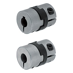
Flexible Couplings - Oldham type, clamping type. (Part Numbers)
Click this image to zoom it.
Move the mouse over the image to zoom
Oldham type flexible couplings with clamping type fastening. They have the option of selecting the keyway at one end only or at both ends. Features selectable alterations to increase the width of the keyway.
- METRIC
- inCAD Components

Part Number
Configured Part Number is shown.

・Materials
| Standard Bore | Keywayed Bore | [ M ]Material | [ A ]Accessories | |||
| d1 (One Side) | d2 (One Side) | d1, d2 (Both Sides) | Hub | Spacer | ||
| MCOC | MCOCLK | MCOCRK | MCOCWK | 304 Stainless Steel Sintered Alloy | Carbon Reinforced Resin | Hex Socket Head Cap Screw |
Specifications
| Part Number | - | Shaft Bore Dia. d1 | - | Shaft Bore Dia. d2 |
| MCOC20 | - | 6 | - | 6 |
| MCOCLK20 | - | 6 | - | 8 |
| MCOCWK20 | - | 8 | - | 10 |
| Part Number | d1, d2 (d1≤d2) [ ! ]Keywayed Bore Type is selectable for diameter 6 or larger | D | D1 | D2 | d3 | L | ℓ | A | F | Clamp Screw | ||||||||||||||||
| Type | No. | M | Tightening Torque (N·m) | |||||||||||||||||||||||
| MCOC MCOCLK MCOCRK MCOCWK | 15 | 4 | 5 | 6 | 14.5 | 15 | 16 | 5.0 | 18.4 | 6.6 | 4.5 | 3.2 | M2.5 | 1.0 | ||||||||||||
| 17 | 5 | 6 | 6.35 | 16.8 | 17.5 | 19 | 7.2 | 24.4 | 9 | 5 | 4 | M3 | 1.8 | |||||||||||||
| 20 | 6 | 6.35 | 7 | 8 | 9.53 | 10 | 20 | 21 | 23 | 8.2 | 27.2 | 10 | 7 | 4.5 | ||||||||||||
| 26 | 6 | 6.35 | 7 | 8 | 9.53 | 10 | 11 | 12 | 26 | 27 | 29 | 12.0 | 30.4 | 11.5 | 8.4 | 5 | M4 | 3.0 | ||||||||
| 30 | 8 | 10 | 30 | 31 | 32 | 13.0 | 33 | 12 | 8.5 | 6 | M5 | 8.0 | ||||||||||||||
| 12 | 14 | 9 | M4 | 4.5 | ||||||||||||||||||||||
| 34 | 10 | 11 | 12 | 14 | 15 | 16 | 34 | 35 | 37 | 13.0 | 34 | 13 | 11 | 6 | M5 | 8.0* | ||||||||||
| 38 | 10 | 12 | 14 | 15 | 16 | 38 | 41 | 41 | 16.0 | 40 | 15 | 11.5 | 7 | M5 | 8.0 | |||||||||||
| 18 | 20 | 13.7 | ||||||||||||||||||||||||
| Part Number | Allowable Torque (N·m) | Angular Misalignment (°) | Lateral Misalignment (mm) | Static Torsional Spring Constant (N·m/rad) | Max. Rotational Speed (r/min) | Moment of Inertia (kg·m2) | Allowable Axial Misalignment (mm) | Mass (g) | |
| Type | No. | ||||||||
| MCOC MCOCLK MCOCRK MCOCWK | 15 | 1.6 | 3 | 0.8 | 90 | 10000 | 5.0x10⁻⁷ | ±0.45 | 15 |
| 17 | 2.2 | 1 | 250 | 1.0x10⁻⁶ | ±0.55 | 28 | |||
| 20 | 3.2 | 1.5 | 340 | 8000 | 2.4x10⁻⁶ | ±0.6 | 40 | ||
| 26 | 6 | 2 | 420 | 6500 | 8.0x10⁻⁶ | 85 | |||
| 30 | 15 | 2 | 1200 | 6200 | 2.0x10⁻⁵ | 100 | |||
| 34 | 16 | 2.5 | 2400 | 6000 | 2.5x10⁻⁵ | 155 | |||
| 38 | 28 | 2.5 | 3500 | 5800 | 8.0x10⁻⁵ | 240 | |||
Price list
■Volume Discount Rate ([ ! ]Round down to nearest one cent.) P.89
[ ! ]For orders larger than indicated quantity, please request a quotation.
| Quantity | 1~9 | 10~14 | 15~19 | 20~29 |
| Discount Rate | Unit Price | 5% | 10% | 18% |
Alterations

More Information

Technical Information
Keyway Dimensions

| Shaft Bore Dia. d1, d2 | b | t | Key Nom. Dim. b x h | ||
|---|---|---|---|---|---|
| Dim. | Tolerance | Dim. | Tolerance | ||
| 6-7.9 | 2 | ±0.0125 | 1.0 | +0.1 0 | 2x2 |
| 8-10 | 3 | 1.4 | 3x3 | ||
| 10.1-12 | 4 | ±0.0150 | 1.8 | 4x4 | |
| 12.1-17 | 5 | 2.3 | 5x5 | ||
| 17.1-20 | 6 | 2.8 | 6x6 | ||
Support Information
MISUMI Coupling Type
| Coupling Type | Disk Tye | With Slit Type | Oldham Type | Jaw Type | Bellows Type | Rigid Type | Universal Joints Type | Chain Couplings Type |
|---|---|---|---|---|---|---|---|---|
| Photo |  |  |  |  |  |  |  |  |
| Shaft Bore Dia | Ø2-60 mm | Ø1.5-35 mm | Ø1-47 mm | Ø3-60 mm | Ø0-62 mm | Ø3-35 mm | Ø1-60 mm | Ø14-55 mm |
| Mortor Recommendation | *Servo Motor *Stepping Motors | *Servo Motor *Stepping Motors | *General Purpose Morter | *Stepping Motors *General Purpose Morter | *Stepping Motors | *Servo Motor *Stepping Motors | *Stepping Motors *General Purpose Morter | *General Purpose Morter |
| Torque | 0.15-800 N·m | 0.05-35 N·m | 0.06-352 N·m | 0.31-1,350 N·m | 0.3-500 N·m | 0.3-206 N·m | 0.25-495 N·m | 100-2,372 N·m |
| Zero Backlash | Excellent | Excellent | Inefficient | Inefficient | Good | Excellent | Inefficient | Inefficient |
| Allowable Angular Misalignment | Good | Good | Excellent | Reasonable | Excellent | Inefficient | Excellent | Reasonable |
| Allowable Lateral Misalignment | Reasonable | Reasonable | Excellent | Reasonable | Reasonable | Inefficient | Inefficient | Reasonable |
| Axial Misalignment | Good | Reasonable | Good | Inefficient | Excellent | Inefficient | Inefficient | Inefficient |
| See all options | Click here | Click here | Click here | Click here | Click here | Click here | Click here | Click here |
For more details on each type of coupling click here
Features
Oldham Couplings
Easy to install with large angular/lateral misalignment allowances characteristics.
- Spacers designed to flex and slide to allow misalignments.
- Larger misalignment allowance ranges compared to the other types, making for easy to adjust for installing.
- High rigidity type has bronze spacer material instead of resin, and has torque capacity 2x of the conventional type.
- Space-Saving Type up to 17% shorter in length contributing to space saving machine designs.
Cautions
Use Precautions
- Make sure to keep misalignment within the allowed range and avoid excessive torque. Otherwise the coupling’s life will be shortened considerably due to plastic deformation.
- For your safety, enclose the revolving parts of equipment with a protective cover.
- If the coupling item generates abnormal metallic noises, immediately turn off the equipment and identify the cause. Such noises may be an indication of improper alignment, shaft interference or a loose screw.
- For applications with a large load fluctuation, apply an adhesive agent on the coupling’s screws to prevent them from loosening. Alternatively, select a coupling of a larger size/load capability.
Compatible Models


Part Number
CAD Data download and 3D preview are not available because the part number has not yet been determined.
- *In order to open the CAD Data download and 3D preview screen, the part number must be fixed.
- Please confirm the part number from "Specification / Dimension"on the left side, and then perform the CAD Data Download / 3D Preview operation.
Loading...
| Part Number |
|---|
| MCOCWK26-LDC[6.1-12/0.1]-[6,6.35,7,8,9.53,10,11,12] |
| MCOCWK26-LDC[6.1-12/0.1]-RDC[6.1-12/0.1] |
| MCOCWK30-[8,10,12,14]-[8,10,12,14] |
| MCOCWK30-[8,10,12,14]-RDC[8.1-14/0.1] |
| MCOCWK30-LDC[8.1-14/0.1]-[8,10,12,14] |
| MCOCWK30-LDC[8.1-14/0.1]-RDC[8.1-14/0.1] |
| MCOCWK34-[10,11,12,14,15,16]-[10,11,12,14,15,16] |
| MCOCWK34-[10,11,12,14,15,16]-RDC[10.1-18/0.1] |
| MCOCWK34-LDC[10.1-18/0.1]-[10,11,12,14,15,16] |
| MCOCWK34-LDC[10.1-18/0.1]-RDC[10.1-18/0.1] |
| MCOCWK38-[10,12,14,15,16,18,20]-[10,12,14,15,16,18,20] |
| MCOCWK38-[10,12,14,15,16,18,20]-RDC[10.1-19/0.1] |
| MCOCWK38-LDC[10.1-19/0.1]-[10,12,14,15,16,18,20] |
| MCOCWK38-LDC[10.1-19/0.1]-RDC[10.1-19/0.1] |
Loading...
Basic Information
| Series Name | Oldham Type | Allowable Misalignment | Angular / Eccentricity / Axial | Application | Standard |
|---|---|---|---|---|---|
| Max. Rotational Speed Range(r/min) | 4001~10000 | Features | High Torque Type / Low Moment of Inertia | Body Material | 304 Stainless Steel Sintered Alloy |
| Category | Coupling Main Body | Allowable Angular Misalignment(deg) | 3 | Buffer Part Material | Carbon Reinforced Resin |
| Operating Temperature(℃) | -40::90 |
Specification/Dimensions
-
Allowable Torque Range(N•m)
-
For Shaft Size d1(mm)
-
For Shaft Size d2(mm)
-
O.D. D(Ø)
-
Overall Length(mm)
-
Allowable Torque(N•m)
-
Max. Rotational Speed(r/min)
-
Allowable Lateral Misalignment Range(mm)
-
Allowable Lateral Misalignment(mm)
-
Shaft Bore Shape
-
Shaft I.D. d1 Change Hole Dia. [LDC] Specified in 0.1mm Increment
-
Shaft I.D. d2 Change Hole Dia. [RDC] Specified in 0.1mm Increment
-
type
- MCOC
- MCOCLK
- MCOCRK
- MCOCWK
-
CAD
- 2D
- 3D
Days to Ship
-
- All
- 8 Days or Less
- 10 Days or Less
Specify Alterations
- The specifications and dimensions of some parts may not be fully covered. For exact details, refer to manufacturer catalogs .
Additional Products in this Category
- Flexible Couplings - Disc type, for servomotor, for high torque, outer diameter of 65 mm.
- Flexible Couplings - High-torque disc, 87 mm outside diameter.
- Flexible Couplings - Oldham type, with large outside diameter.
- Flexible Couplings - Spacer for Oldham coupling type MFJ/MFJC series.
- Flexible Couplings - Slotted type, standard length or compact.
- Flexible Couplings - Oldham type, short clamping.
- Flexible Couplings - Double disc type.
- Flexible Couplings - Single disc, clamp-on, XHS/XHW/XHW-L series.
Complementary Products


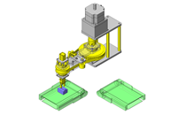
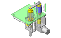
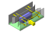
MISUMI Unit Example related to this product
Tech Support
- Technical Support
- Tel:+52-442-672-7661 ext. 2 then wait and dial 4
E-mail: soportetecnico@misumimex.com - Mon. - Fri. 8 a.m. - 6 p.m.
- Technical Inquiry
How can we improve?
How can we improve?
While we are not able to respond directly to comments submitted in this form, the information will be reviewed for future improvement.
Customer Privacy Policy
Thank you for your cooperation.
While we are not able to respond directly to comments submitted in this form, the information will be reviewed for future improvement.
Please use the inquiry form.
Customer Privacy Policy