(!)Due to Microsoft's end of support for Internet Explorer 11 on 15/06/2022, this site does not support the recommended environment.
Mon. - Fri. 8 a.m. - 6 p.m.
All Categories
-
Automation Components
Automation Components
Show all categories of Automation Components-
Linear Motion
-
Rotary Motion
-
Connecting Parts
-
Rotary Power Transmission
-
Motors
-
Conveyors & Material Handling
-
Locating, Positioning, Jigs & Fixtures
-
Inspection
-
Sensors, Switches
-
Pneumatics, Hydraulics
-
Vacuum Components
-
Hydraulic Equipment
-
Spray Equipment And Accessories
-
Pipe, Tubes, Hoses & Fittings
-
Modules, Units
-
Heaters, Temperature Control
-
Aluminum Extrusions, Framing, Support & Posts
-
Casters, Leveling Mounts, Posts
-
Doors, Cabinet Hardware
-
Springs, Shock Absorbers
-
Adjustment/Fastening Components, Pins, Magnets
-
Antivibration, Soundproofing Materials, Safety Products
-
- Fasteners
- Materials
-
Wiring Components
Wiring Components
Show all categories of Wiring Components-
LAN Cables / Industrial Network Cables
-
Equipment Specific Cables
-
Cordsets
-
Computer & AV Cables
-
Wire/Cable
-
Connector (General Purpose)
-
Crimp Terminal Components
-
Cable Organization
-
Cable Gland Components
-
Cable Bushing/Clip/Sticker
-
Screw/Spacer
-
Cable accessories
-
Tube
-
Electrical Conduits
-
Duct/Wiring
-
Electrical Wiring Tools
-
Dedicated tools
-
Soldering supplies
-
- Electrical & Controls
-
Cutting Tools
Cutting Tools
Show all categories of Cutting Tools-
Carbide End Mill
-
HSS End Mill
-
Concrete Drill Bits
-
Milling Cutter Insert / Holder
-
Core Drill Bits
-
Customized Straight Blade End Mill
-
Dedicated Cutter
-
Crinkey Cutters
-
Turning Tool
-
Drill
-
Cutting Tool Accessories
-
Screw Hole Related Tools
-
Reamer
-
Electric Drill Bits
-
Chamfering, Centering Tool
-
Hole Saws
-
Magnetic Drill Press Cutters
-
Step Drills
-
Wood Drills & Cutters
-
-
Processing Tools
- Packing & Logistics Storage Supplies
- Safety Products
-
Research and Development & Cleanroom Supplies
Research and Development & Cleanroom Supplies
Show all categories of Research and Development & Cleanroom Supplies - Press Die Components
-
Plastic Mold Components
Plastic Mold Components
Show all categories of Plastic Mold Components-
Ejector Pins
-
Sleeves, Center Pins
-
Core Pins
-
Sprue bushings, Gates, and other components
-
Date Mark Inserts, Recycle Mark Inserts, Pins with Gas Vent
-
Undercut, Plates
-
Leader Components, Components for Ejector Space
-
Mold Opening Controllers
-
Cooling or Heating Components
-
Accessories, Others
-
Components of Large Mold, Die Casting
-
-
Injection Molding Components
Injection Molding Components
Show all categories of Injection Molding Components-
Purging Agent
-
Injection Molding Machine Products
-
Accessories of Equipment
-
Auxiliary Equipment
-
Air Nippers
-
Air Cylinders
-
Air Chuck for Runner
-
Chuck Board Components
-
Frames
-
Suction Components
-
Parallel Air Chuck
-
Special Air Chuck
-
Mold Maintenance
-
Heating Items
-
Heat Insulation Sheets
-
Couplers, Plugs, One-touch Joints
-
Tubes, Hoses, Peripheral Components
-
- Webcode Seach | Series
-
#CODE
- Discontinued Products
Loading...
- inCAD Library Home
- > No.000183 Removable Turntable
No.000183 Removable Turntable
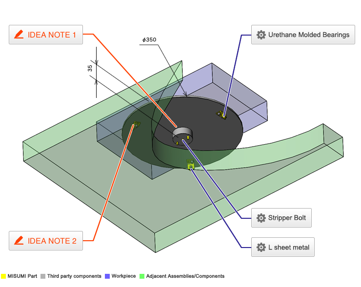
Bottom view of removable turntable.
Relevant category
- * Unit assembly Data consists of some sub-assemblies.
It is configured so that each sub-assembly unit can be used as it is or edited.
Application Overview
Purpose
- Purpose
- Used for product inspection/repair.
- Operation
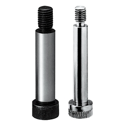
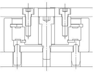
- Product inspection and repair are conducted on a workbench. If the turntable is not needed, it is removable by loosening center turntable bolt. When re-installing, use the two center locating pins to position the table and tightening the center bolt.
Points for use
- The turntable is rotated manually.
Target workpiece
- Shape: Block
- Size: W 430 x D 250 x H 70 mm
- Weight: 6 kg
Design Specifications
Operating Conditions or Design Requirements
- Turntable O.D.: φ350mm
- External size (workbench): W 700 x D 600 x H 170 mm
Selection Criteria for Main Components
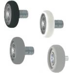
- Select size for urethane molded bearings to support motions and to prevent deflection of the turntable.
Design Evaluation
Verification of main components
- Verify bearing durability or life span based on load rating.
- Calculate life span of the bearing
- Life span for bearings (106 rotations): L = (Cr/Pr)³ , where
Cr=7250N - Basic Dynamic load rating for B6906ZZ (from catalog)
Pr- Radial Dynamic Equivalent load (need to calculate based on application loads) - Other conditionals values:
Workpiece weight: M = 6 kg
Gravitational acceleration: g = 9.8 m/s²
Gravity by the workpiece: W = M x g = 6 x 9.8 = 59 N
Manual force used to move turntable: Assume to be Q = 200 N - Radial Dynamic Equivalent load
Pr =X×Fr + Y×Fa, where Fr-radial load, Fa-thrust load and X=1 and Y=2.3 are radial and thrust factor (values from catalog) - Assume that force acting on the bearing, Po = M + Q, acts only in the z-axis direction (thrust load), and let radial load Fr=0N, then we obtain the following:
Thrust load: Fa=Po=M+Q=259N、then
Pr=1×Fr+2.3×(M+Q)=1×0+2.3×259=596N - Bearing rated life L = (Cr/Pr)³ = (7250/596)³ = 1800 (10? rotations), has sufficient margin for our application.
- Life span for bearings (106 rotations): L = (Cr/Pr)³ , where
Other Design Consideration
- Securing repeatability of the turntable position and fixing the turntable with one bolt.
- In this example two round locating pins are used for turntable positioning, combination of round and diamond pin can also be effectively used.
Explore Similar Application Examples
-
Relevant category
-
Relevant category


