Stamping die processes are known for their speed, consistency and cost-effectiveness in mass production, are a crucial part of modern manufacturing.
With MISUMI, you can find great design flexibility. Our online store offers you the opportunity to configure press die components based on your design requirements.
Stamping
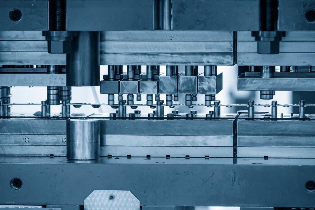
Stamping is the manufacturing process of cutting or piercing flat materials into a finish product. The Stamping process can be done by using a press that can be hydraulic or mechanical.
Common metal stamped components include:
- Automotive components (panels, frames, hinges, support pillars, etc.)
- Household Appliances
- Connectors/Terminals/Electronics
- Paper clips, coins, etc.
Dies
Dies are specialized tools employed in manufacturing processes to cut or shape a material or final product using a press. Dies are customized to mass produce the specific item that is required.
MISUMI Die components are the main parts that make up a stamping die that goes into the press, hence the term “press dies”.
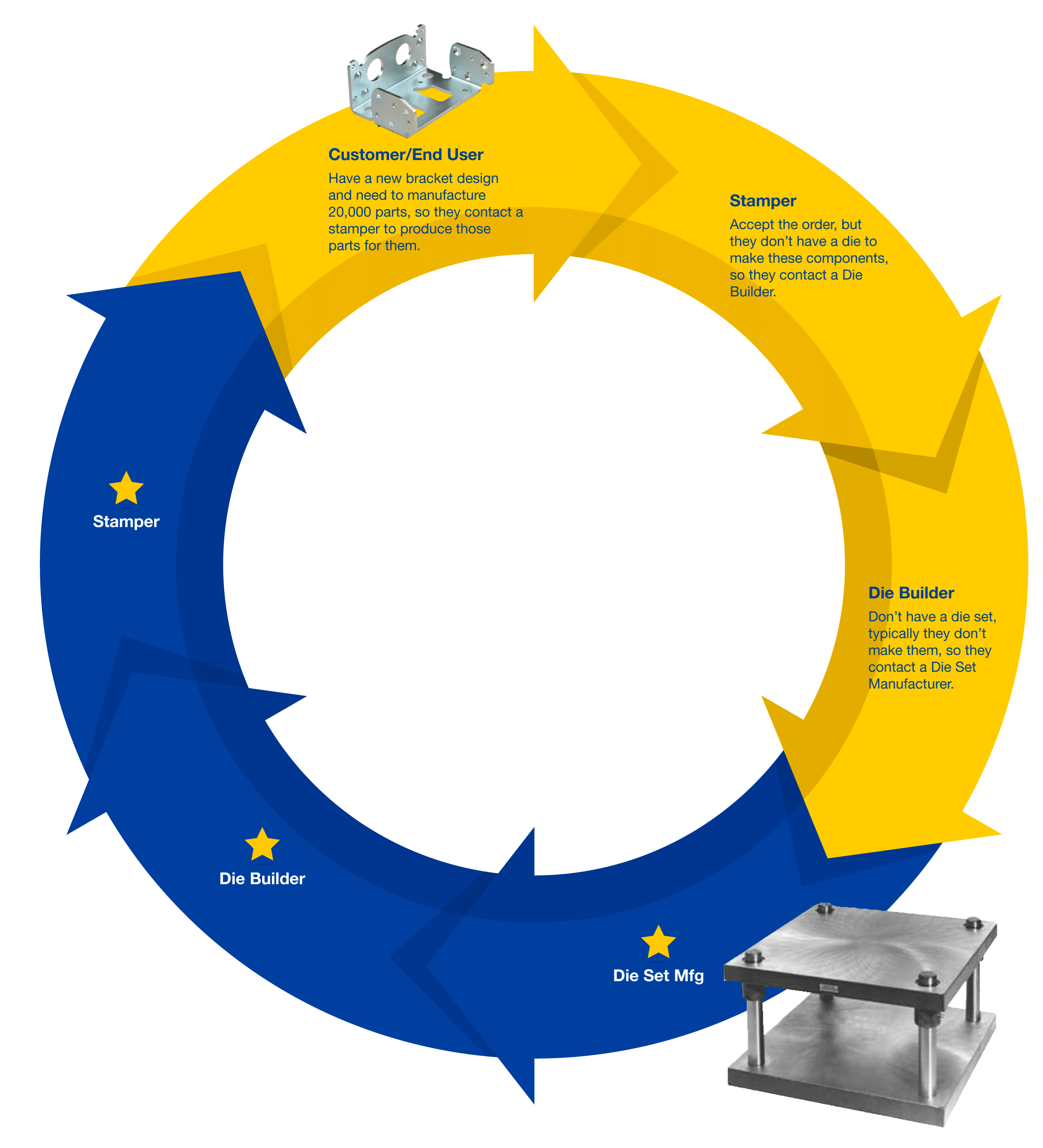
Typical Tooling Process
Different Operations & Die Types
Operations
Trimming
The perimeter edge of a form is cut away to conform with the
desired shape.
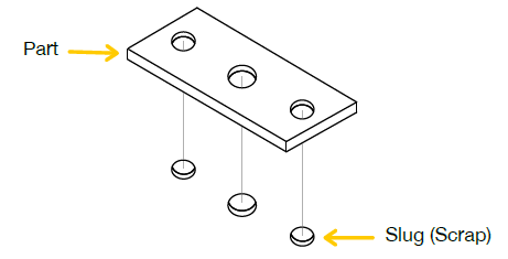
Piercing
The piece that is removed is scrap and what remains is the
workable part.
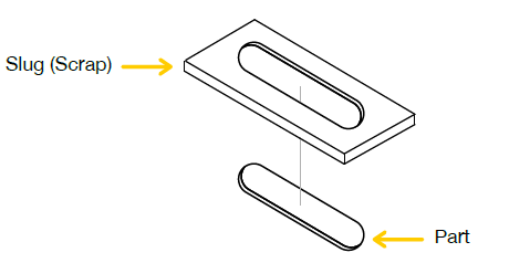
Blanking
The piece punched out becomes the workable part.
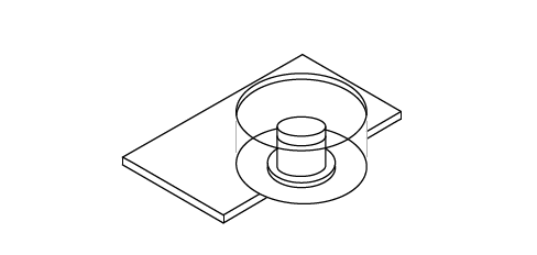
Drawing/Forming
The material is getting pushed and formed into a die.
Die Types
- Single hit dies: The material progresses across the die and each time it cycles it adds an additional feature to the die until get the final stage.
- Progressive dies: Has several dies that are activated together. The metal strip, is fed through, producing a continuous stream of parts. The stress on the metal is distributed evenly over multiple operations. The equal distance between them is called progression.
- Compound dies: Perform two or more operations at the same time. Better option for high-volumen production of simple metal parts.
- Transfer/Tandem dies: Mostly used for forming large automotive components like door panels or even in the appliance industry.


Punches
Punches are tools used to pierce round or shaped hole into material, when paired with a die/matrix.
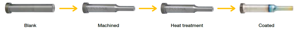
MISUMI offers configurable punches that start from blanks and then you can:
- Cut to length
- Tip machined to size/shape
- Alterations (options)
- Heat treatment
- Surface treatment applied (optional)
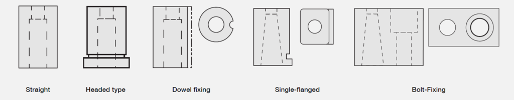
Mounting Styles & Terminology
Headed
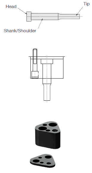
Headed-mount punches have a flange at the end of the punch. To remove this type of punch, it is necessary to unbolt the retainer where it is mounted and pull the punch back to the counterbore hole.
Ball Lock
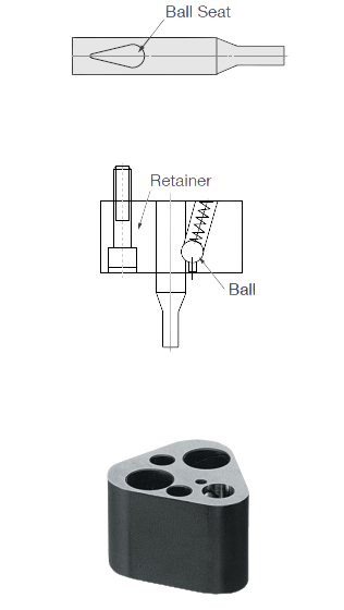
Ball Lock punches are ease to remove using a
tool that applies pressure to the ball from the top,
which then releases the punch without the need
to unbolt anything. The installation is just as easy;
you just need to press it back into position.
Key Groove
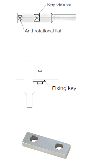
Key Groove punches have the benefit of allowing
several punches to be processed in a very limited
space.
Punches Product Feactures
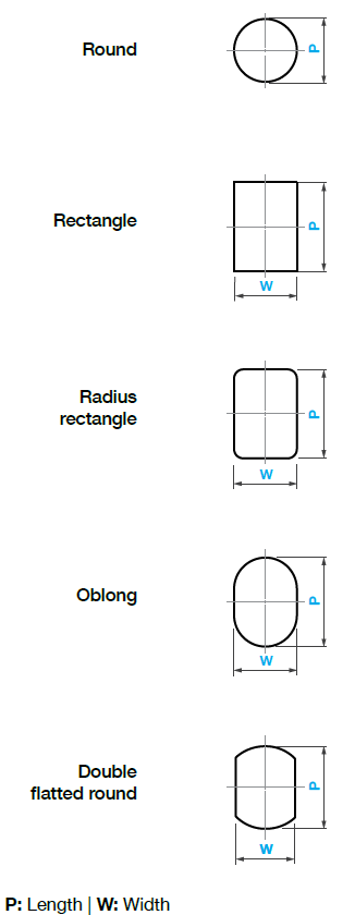
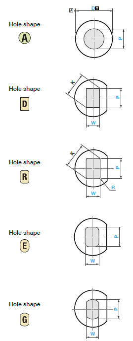
5 Standard Shapes
5 Standard shapes and 53 Special shapes.
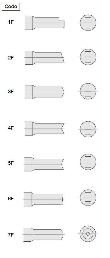
Punch Tip Shea Angle Alterations
Shear angles to reduce tonnage force and shock.
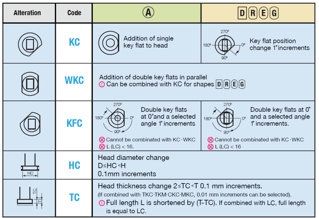
Head Alterations
Key flat included on shaped punches to maintain correct punch orientation.
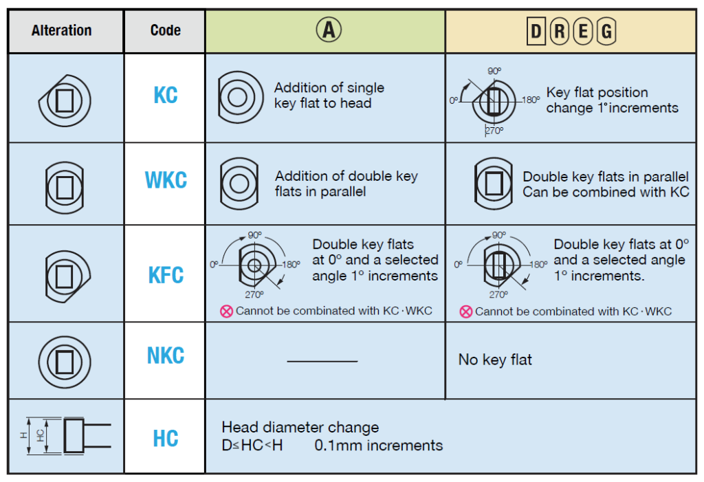
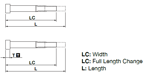
Head Alterations
Standard alterations to modify overall length.
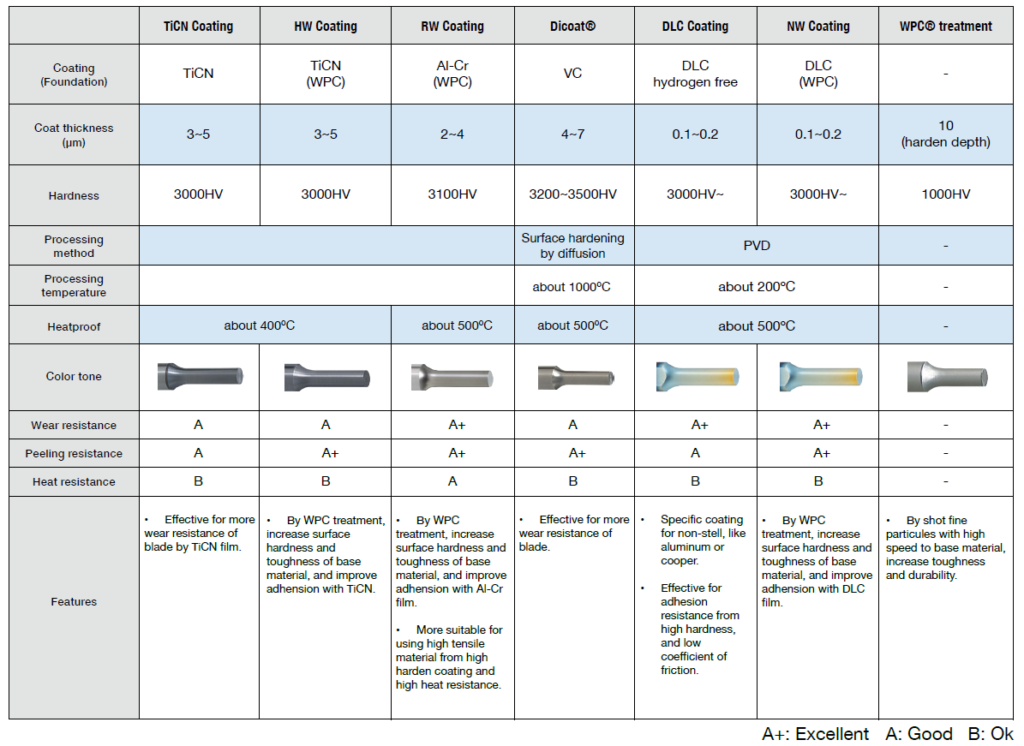
Surface Treatments
Coatings are used to improve the life/wear properties of the punch and vary vastly by application.
It must be taken into consideration the price increase compared to the life increase of the punches.
- Titanium Carbonitride (TiCN) – Hard, wear-resistant ceramic coating considered the industry standard. Most used in the industry for years. Recent innovations for materials have called for improved coatings.
- WPC® – This treatment involves colliding fine particles approximately 0.04 ~ 0.2 mm in size with the metal surface at speeds of 100 m/s or more, generating high
residual compressive stress in the area close to the surface of the punch. This improves the fatigue strength of the punch, yielding a high resistance to tip breakage
and chipping. This coating helps other coatings adhere better to the refined surface. - Aluminum and Chromium (Al-Cr) – Coatings that help improve corrosion and wear resistance. Ideal for high tensile strength applications (stainless).
- DLC – Diamond like coating that takes advantage of the two main chemical properties of the carbon: the hardness of the diamond and the sliding effect of graphite.
Ideal for aluminum and other non-ferrous materials.
Button Dies
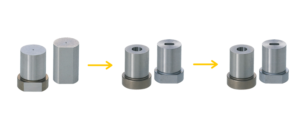
Button dies are complementary components of a punch. Button dies are a tool used to pierce, round or shaped a hole in material, always paired with a punch.
MISUMI button dies are configurable and can be modified from a blank into a final form by selecting:
- Length
- Blanks made with 0.3mm center hole for wire EDM finishing
- Alterations (optional)
- Heat treatment
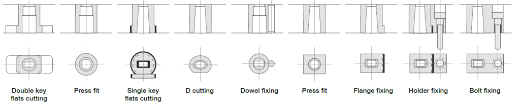
Mounting Styles
All MISUMI button dies have the same mounting options as punches, in addition to press-fit mounting.
Detailed Mounting Styles Info
Button Die Product Features
5 Standard Shapes
5 Standard shapes and 53 Special shapes.
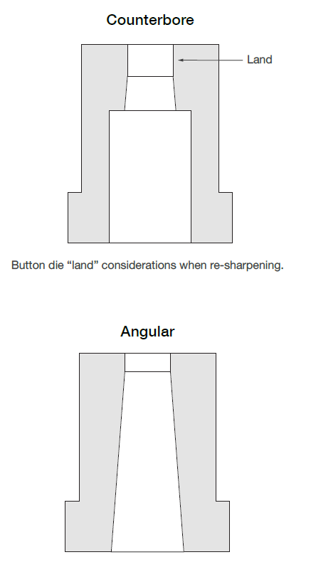
Button Die Slug Relief
Button dies have a critical function to allow
slug to freely fall through and not cause jam
or clog.
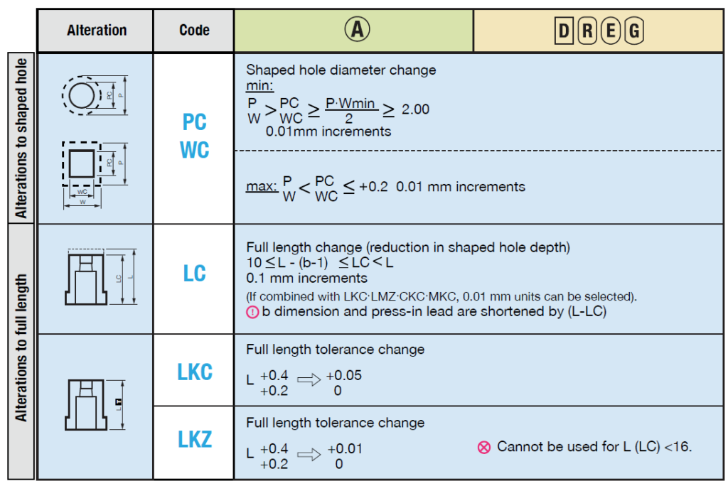
Head Alterations
Other Alterations
Material
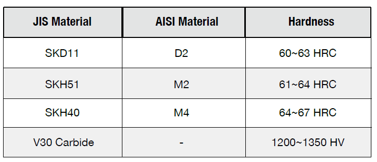
MISUMI offers tool steel and carbide punches/button dies.
- Tool steel (D2, M2, M4) – Ideal for high tensile strength materials (materials containing Iron).
- Carbide – Ideal for non-ferrous materials due to wear properties.
Toughness is the ability to absorb energy, while wear resistance is related to hardness.
Not all materials are suitable for coatings due to tempering/processing temperature.
- Coatings are not offered on buttons due to the PVD process. (PVD: Physical vapour deposition).
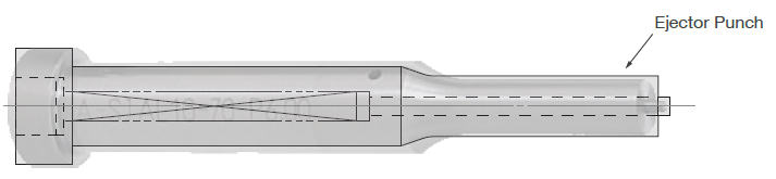
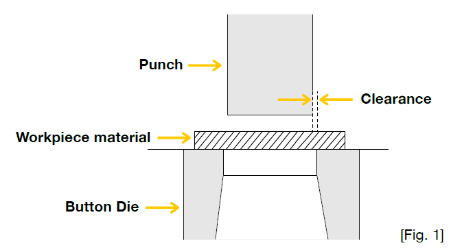
Ejector Punches & Clearances
Clearance is a critical area for selecting punches and button dies; the gap between the punch and the die, as shown in Fig. 1.
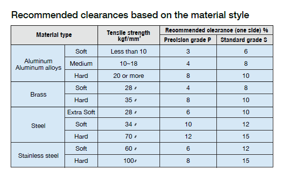
Clearance is measured as a function of material thickness:
- Tight clearance will produce sharper hole (regular clearance)
- Loose clearance will extend the life of the punch (engineered clearance)
For many years, toolmakers used 5% of the stock thickness per side as a standard punch to die clearance. This provided an acceptable burr height and slug control. Research and testing have revealed that a radical increase in punch to die Clearance can reduce burr height to the lowest point while increasing tool life by several times.
The side effect of this approach is slug pulling. A spring-loaded ejector pin extending from the center of the punch face will solve the slug pulling in most cases.
When a pierce punch creates a hole, it produces scrap, called a slug. When the slug sticks to the face of the punch during withdrawal, comes out of the button, lower matrix, it’s called slug pulling.

Tech Support
Tel: +52 442 672 7661 Ext. 2 then wait and dial 4
E-mail: soportetecnico@misumimex.com
Mon.- Fri. 8 a.m. – 6 p.m.