Rotary Motion and Power Trasnmission
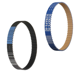
TIMING BELTS
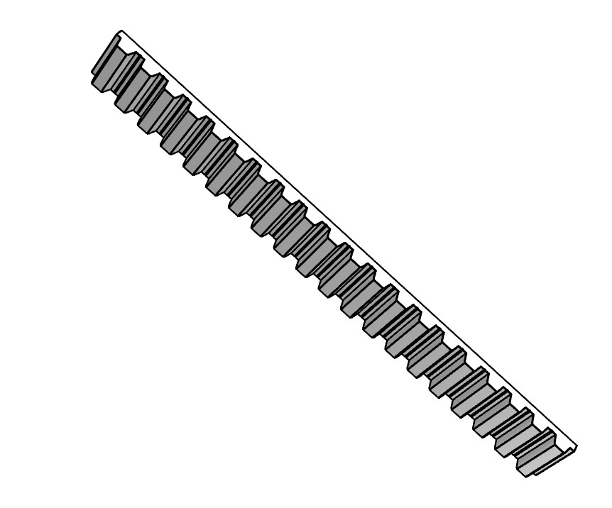
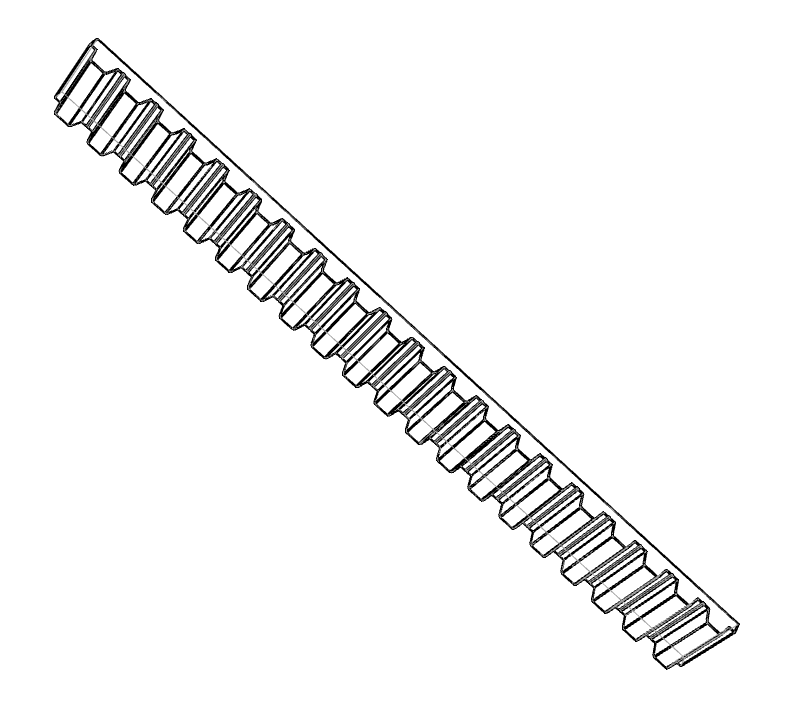
Also known as toothed belt, it is a belt with teeth on its surface that is used in transmission systems to synchronize movement.
Applications
Timing pulleys are used in various automation and control system applications where precise synchronization of motion is required, some of these applications are:
- Robotics: In industrial robots and robotic automation systems, timing pulleys are used to synchronize the movement of the robot’s axes and joints. This ensures precise and coordinated control of robot movements in applications such as welding, assembly, handling and palletizing.
- Printing and labeling: In automated printing and labeling equipment, timing pulleys are used to synchronize the movement of the print rollers, paper feeders and labeling systems. This ensures accurate printing and labeling in each job cycle.
- Packaging: In automated packing and packaging machines, timing pulleys are used to synchronize the movement of machine components such as feeders, sealers and cutting systems. This ensures accurate and efficient processes.
MISUMI inCAD Library
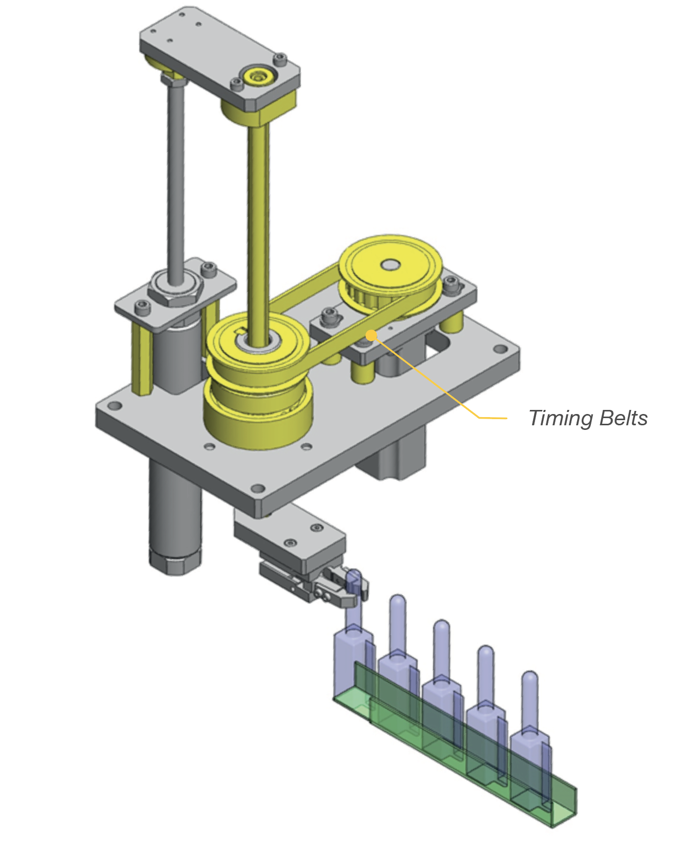
Example No.000032
In this assembly the machine picks up a part to
position it in the other row.
The timing belt is responsible for transmitting the rotary motion
between the motor and the shaft.
Features
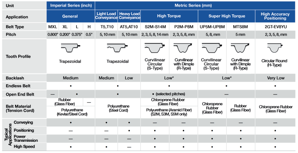
Timing belts are identified by their profile type or, in other words, tooth shape and pitch (distance between tooth centers) and each profile has a serial name to identify it. Be sure to match the belt type with the pulley type.
| MXL | XL | L | H | T5, T10 | AT5, AT10 | S2M-S14M | P2M-P5M | UP5M-UP8M | MTS8M | 2GT-EV8YU |
|---|---|---|---|---|---|---|---|---|---|---|
| 0.800″ | 0.200″ | 0.375″ | 0.5″ | 5, 10mm | 5, 10mm | 2,3,5,8 14mm | 2,3,5, 8mm | 5, 8mm | 5mm | 2,3,5, 8mm |

Pulley Series
The series is what distinguishes each belt type. Each series defines a tooth center distance, tooth geometry, characteristics and recommended applications:
Backlash
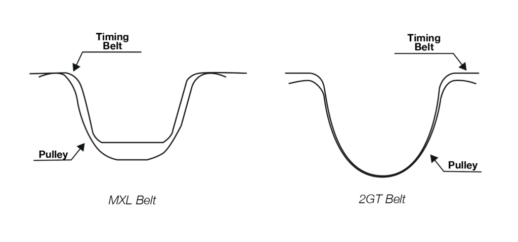
Backlash: Backlash that each belt has in relation to its pulley, the lower the backlash, the more precise the movement of the system is ensured. A belt with low backlash is recommended for positioning and precision applications.
Dimensions to Consider
Belt width
- The belt width(*A) can change the power transmission capacity.
- The same width value is taken for the selection of its
respective sheave. - This measurement can be in millimeters or inches
depending on the belt series.
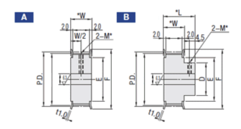
Number of teeth
- The number of teeth will define the length of the belt.
- To calculate the length, the following formula is used:
| MXL | XL | L | H | T5, T10 | AT5, AT10 | S2M-S14M | P2M-P5M | UP5M-UP8M | MTS8M | 2GT-EV8YU |
|---|---|---|---|---|---|---|---|---|---|---|
| 0.800″ | 0.200″ | 0.375″ | 0.5″ | 5, 10mm | 5, 10mm | 2,3,5,8 14mm | 2,3,5, 8mm | 5, 8mm | 5mm | 2,3,5, 8mm |
MISUMI Benefits
- Configurable components
Standard and globally valid part number 3D
- 2D/3D CAD download in different formats (STEP, SolidWorks, CATIA, Inventor, AutoCAD)
- Preview
- Quotations and direct purchases from our online store
Related Products