Linear Motion
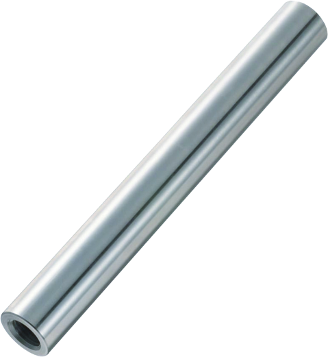
LINEAR SHAFTS
A linear shaft is a mechanical component used to provide linear motion in linear motion systems. machinery and devices. It is a rigid and elongated structure that allows the rectilinear displacement of a load or component along its length.
APPLICATIONS
Linear shafts are used in a wide variety of industrial applications:
- Industrial machinery: Used in manufacturing machines, such as machine tools, industrial robots, 3D printers, laser cutters, packaging machines, assembly equipment, among others. Allow precise and controlled movement of components to perform specific tasks.
- Automation and robotics: Enable linear movement of robots and moving parts of automated systems. Can be used in assembly lines, palletizing systems, material handling systems, etc.
- Packaging: Move products during the process. Provide accurate and repeatable movements to ensure efficient packaging.
- Food industry: Used in food processing and packaging equipment, such as filling, dosing and cutting machines. Help automate production processes and ensure accuracy in food handling.
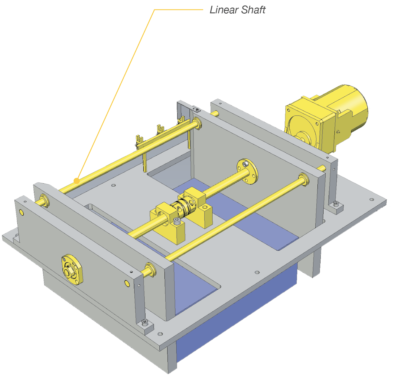
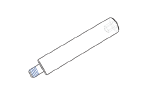
Example SSFJ12-495| MISUMI inCAD Library
In this application we see how the machine automatically
adjusts the distance between the workpiece guides. All the
movement is linear.
Linear shafts ensure that the travel of the plates is completely
linear.
FEATURES
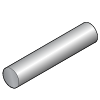
Straight
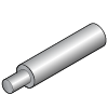
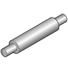
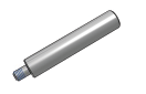
One End Stepped
Both End Stepped
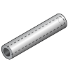
Hollow
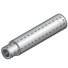
Hollow One End Stepped
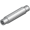
Hollow Both Ends Stepped
Linear shafts can have different shapes and machinings, depending on the specific application and design requirements. Below are some of the common shapes and machinings:
- Straight shafts: The most common linear shafts are round in shape and are machined from cylindrical bars. These shafts may have a constant diameter throughout their length or may have variations in diameter to accommodate different load and stiffness requirements.
- End machining: the ends of linear shafts are usually machined to allow attachment and connection to other components. Typical end machining includes threading, chamfering, drilling or custom machining according to the requirements of assemby and fastening.
- One End Stepped
- Both Ends Stepped
- Hollow shafts: Some linear shafts are machined with a hollow bore. This allows cables, pipes or other items to pass through the shaft, facilitating system integration and cable protection in automation applications.
- Hollow and One End Stepped
- Hollow on Both Ends
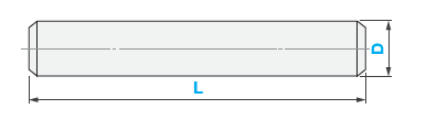
D
from 3 to 50mm (1/4” to 1-1/2”)
L
from 65 to 1500mm (0.75” to 60”)
TOLERANCES
h5, g6, f8
END SHAPE
APPLIES TO BOTH SIDES (RIGHT/LEFT)

No Machining

Tapped

Threaded

Set Screw Groove

Retaining Ring Groove

Keyway

Tapped Holes

Hex Hole

Tapered
MISUMI’s linear shafts are configurable, making them adaptable to your specific application needs. This includes shaft length, special machining, custom ends, materials, finishes, among others.
MATERIALS AND FINISHES
Linear shafts can be manufactured in a variety of materials, depending on application requirements and operating conditions.
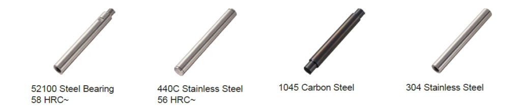
- Carbon steel: It is one of the most widely used materials for the manufacture of linear shafts. It is durable, tough and has good tensile strength. Carbon steel shafts can be suitable for general applications with moderate loads.
- Stainless steel: Highly corrosion resistant, making it a popular choice for applications in wet or corrosive environments. Stainless steel shafts are common in industries such as food, pharmaceutical and chemical.
- Bearing Steel: Offers higher strength and hardness compared to carbon steel. These shafts are suitable for applications with heavier loads or requiring higher wear resistance
In some cases, shafts may be coated with materials such as chromium or nickel to improve their tribological properties
(friction, wear, lubrication) or to protect them against corrosion.
- Not hardened
- Chrome finish
- Low temperature black chrome Nickel
- Plating without electrodes
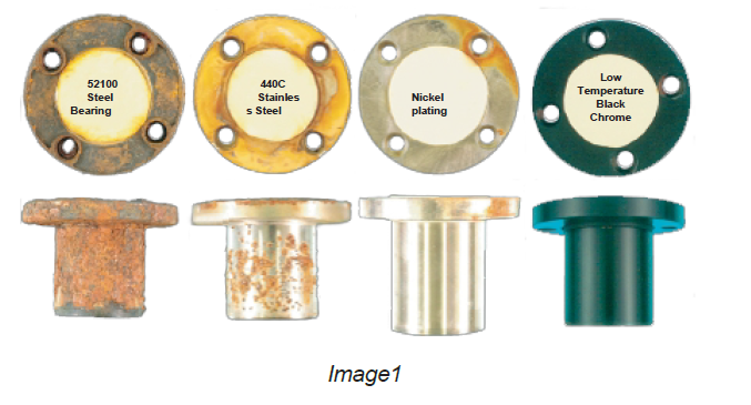
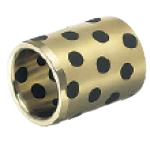
Image 1. Test of 168 hours in salt water. Bushings of different materials and with different surface finishes.
MISUMI BENEFITS
RELATED PRODUCTS